Research on Improvement Methods for Driven System of Bio-Inspired Aircraft to Increase Flight Speed
[ad_1]
Figure 1.
Design process of mechanical transmission flapping mechanism.
Figure 1.
Design process of mechanical transmission flapping mechanism.
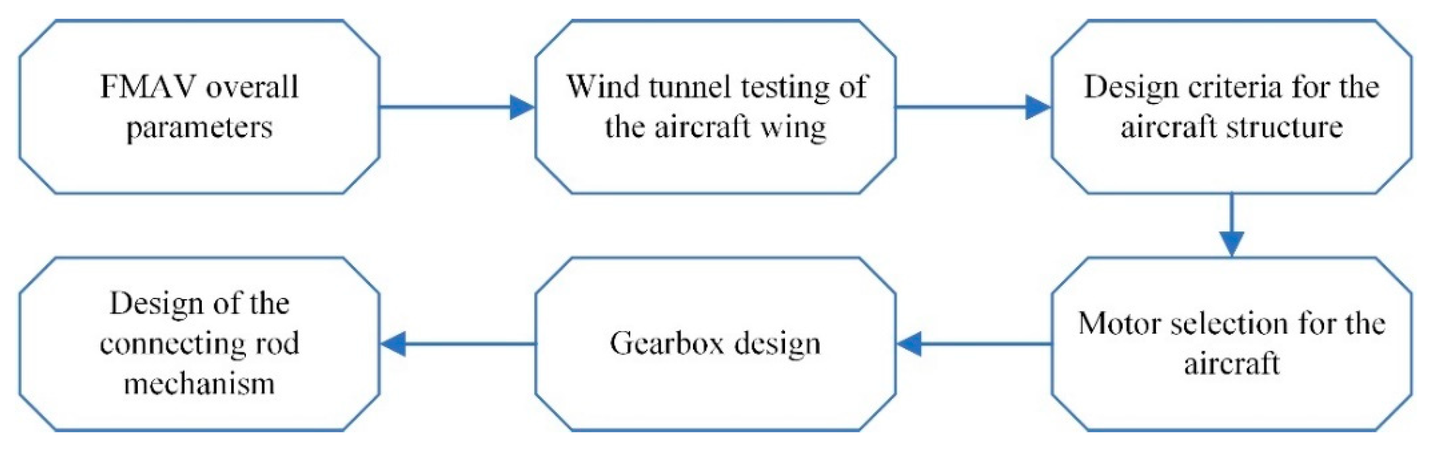
Figure 2.
The propulsion system of the “Dove” aircraft.
Figure 2.
The propulsion system of the “Dove” aircraft.
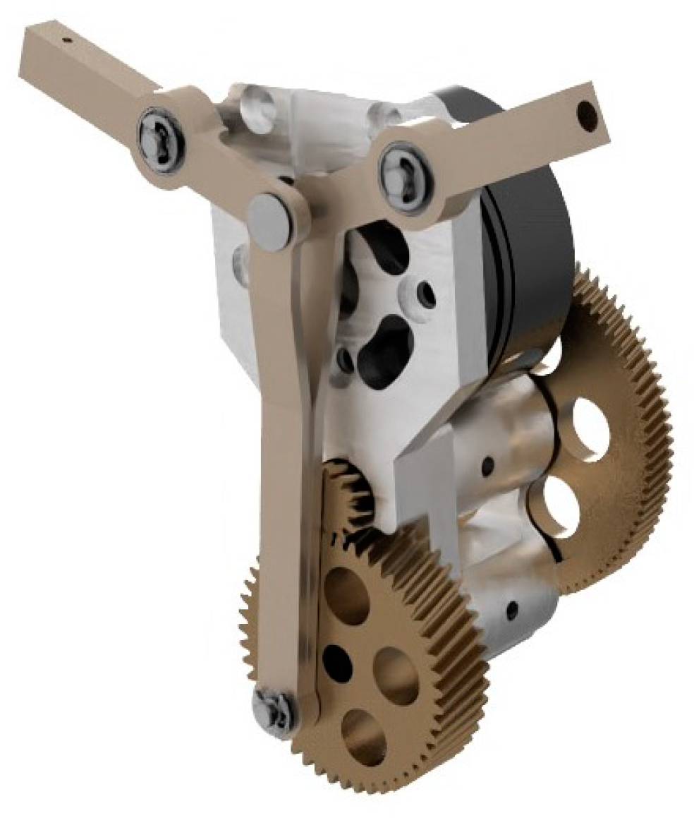
Figure 3.
Testing of wing-flapping frequency in the “Dove” mechanism.
Figure 3.
Testing of wing-flapping frequency in the “Dove” mechanism.
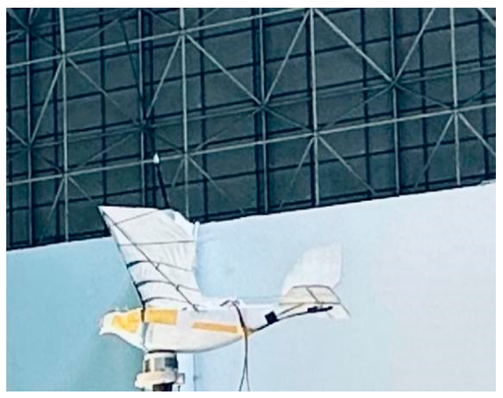
Figure 4.
Actual wing-flapping frequency of the “Dove” at different voltages.
Figure 4.
Actual wing-flapping frequency of the “Dove” at different voltages.
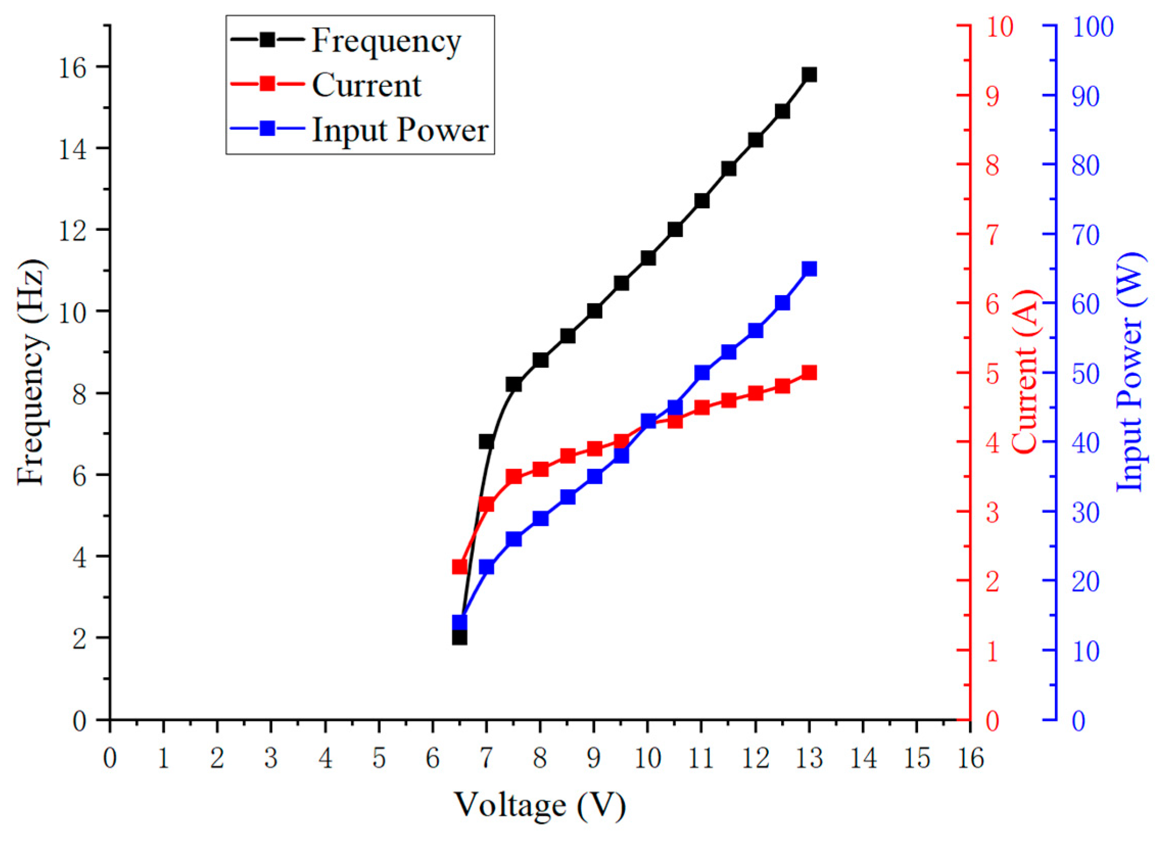
Figure 5.
The relationship between motor voltage, motor current, and wing-flapping frequency.
Figure 5.
The relationship between motor voltage, motor current, and wing-flapping frequency.
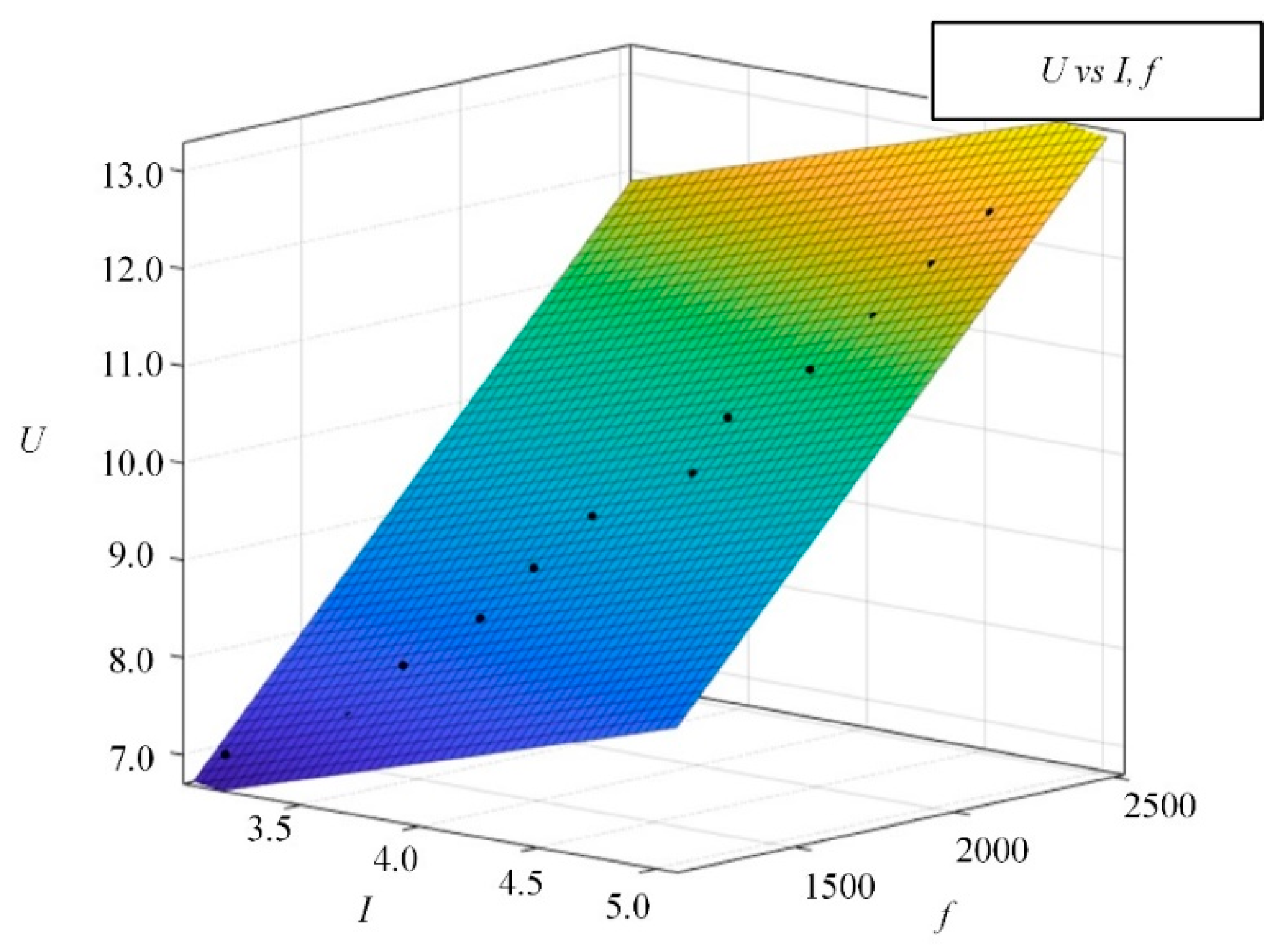
Figure 6.
Power transmission flowchart of the drive system.
Figure 6.
Power transmission flowchart of the drive system.

Figure 7.
Motor efficiency of different motors at various voltages.
Figure 7.
Motor efficiency of different motors at various voltages.
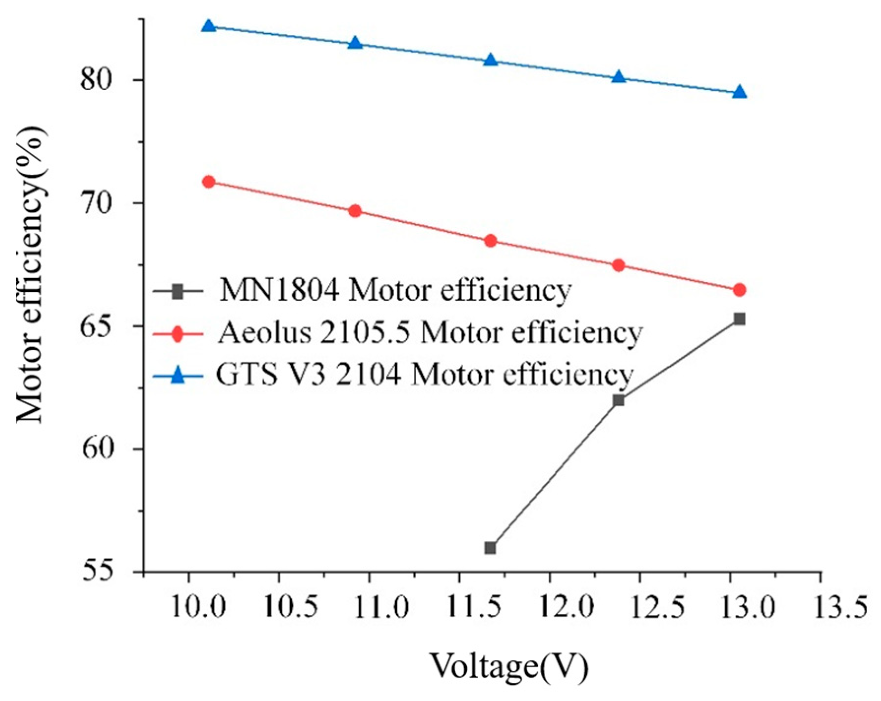
Figure 8.
Torque transmission process diagram.
Figure 8.
Torque transmission process diagram.
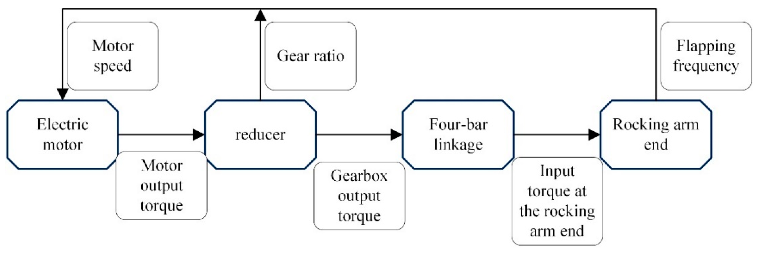
Figure 9.
Feasible range for gear ratio selection of GTS V3 2104 motor.
Figure 9.
Feasible range for gear ratio selection of GTS V3 2104 motor.
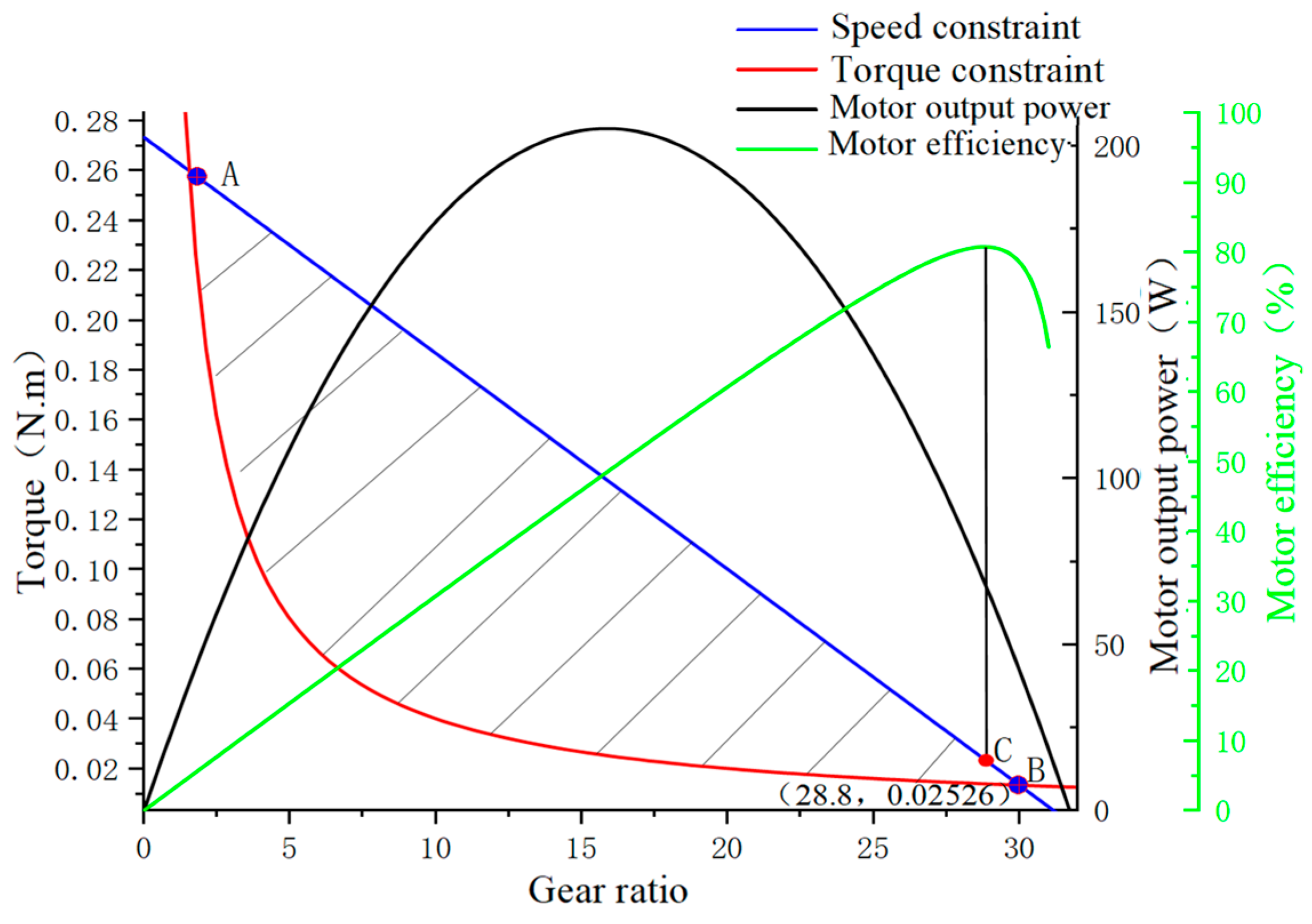
Figure 10.
Flight test prototype’s drive system.
Figure 10.
Flight test prototype’s drive system.
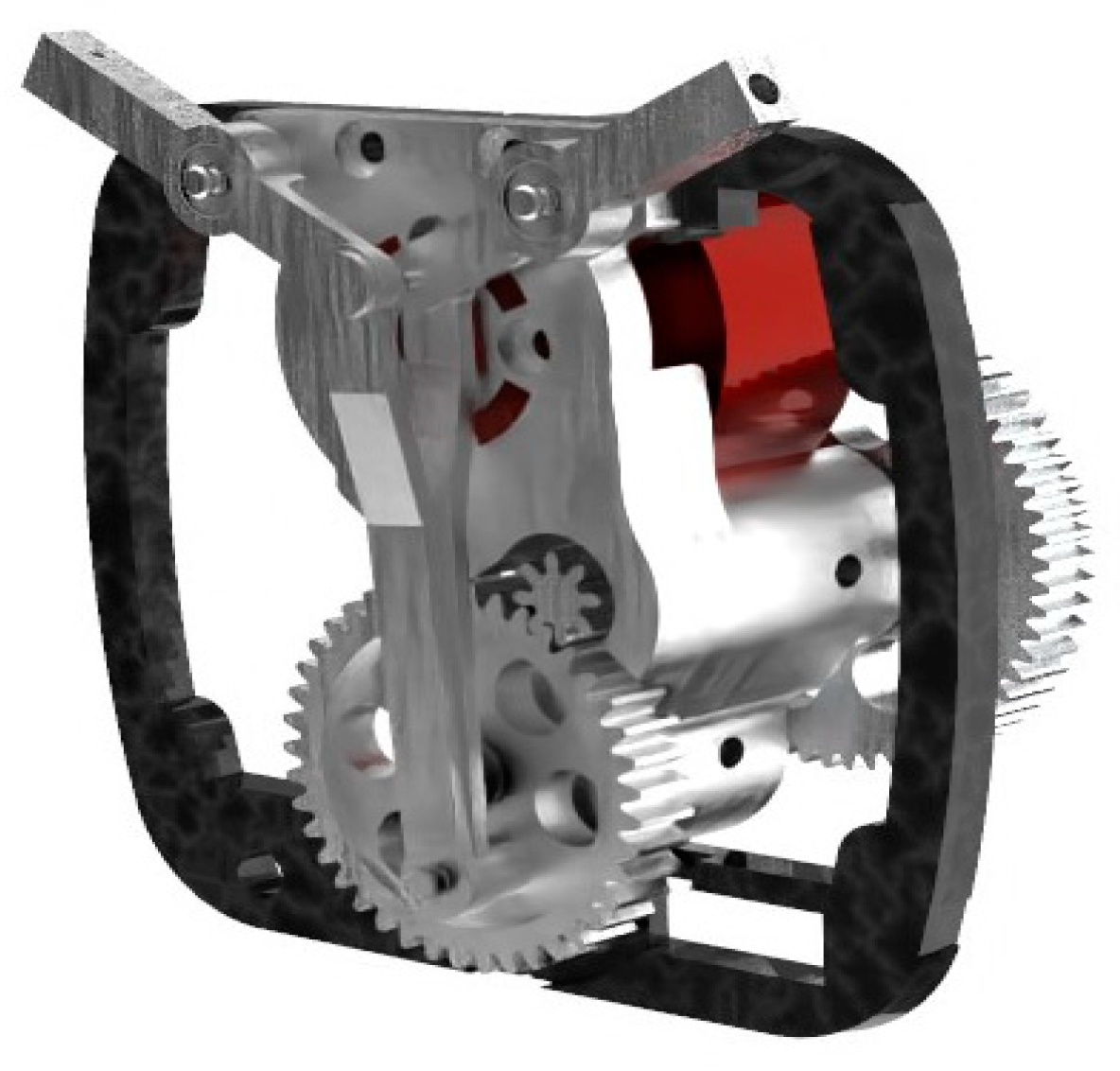
Figure 11.
Aircraft test prototype.
Figure 11.
Aircraft test prototype.
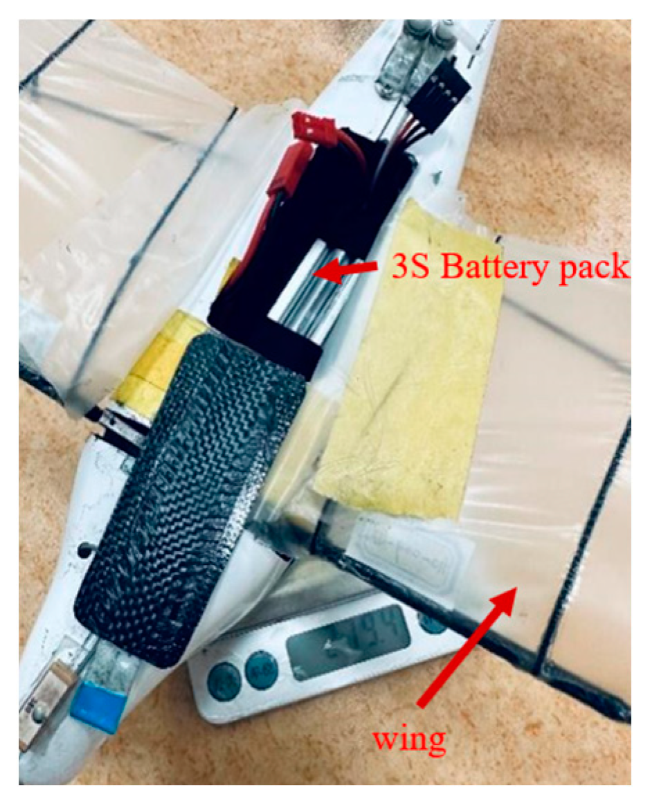
Figure 12.
Specialized wind tunnel for flapping-wing aircraft.
Figure 12.
Specialized wind tunnel for flapping-wing aircraft.
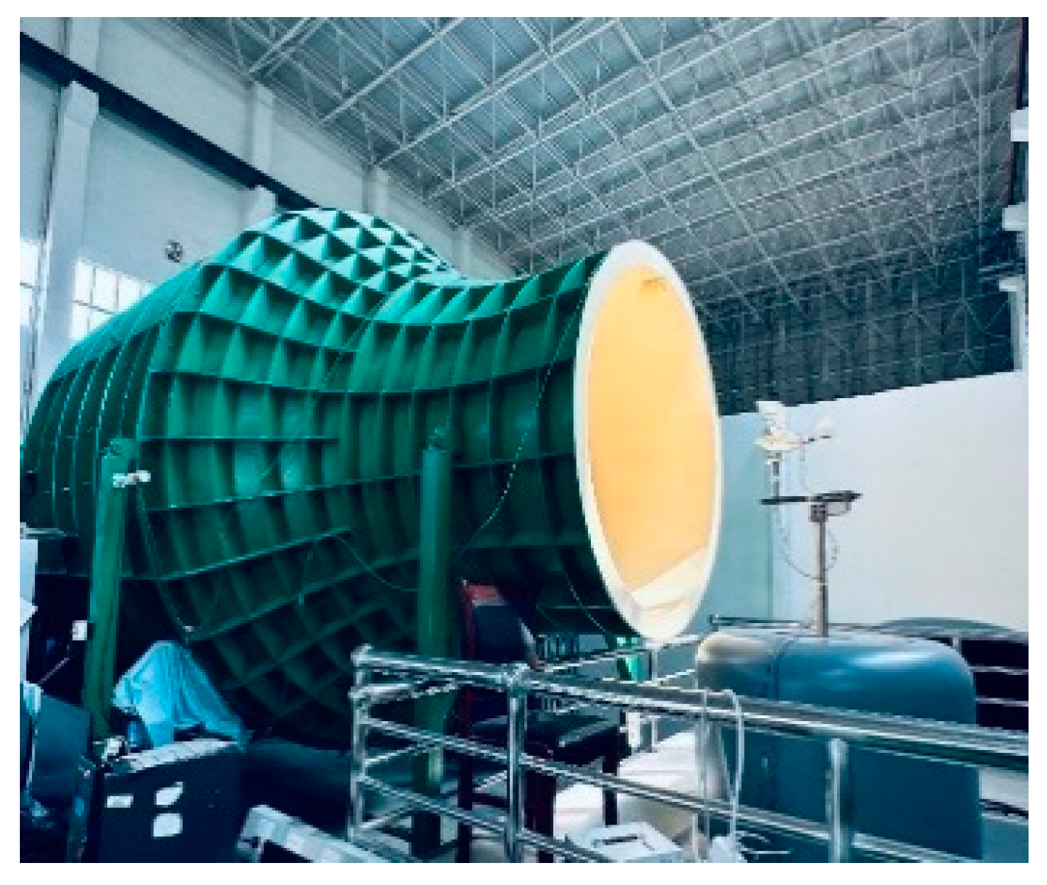
Figure 13.
Current sampling system.
Figure 13.
Current sampling system.
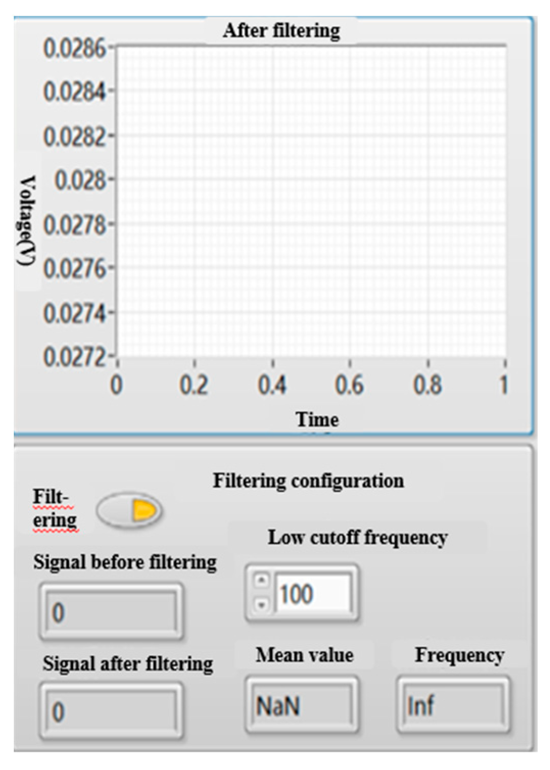
Figure 14.
Wind tunnel load test diagram of the flight test prototype.
Figure 14.
Wind tunnel load test diagram of the flight test prototype.
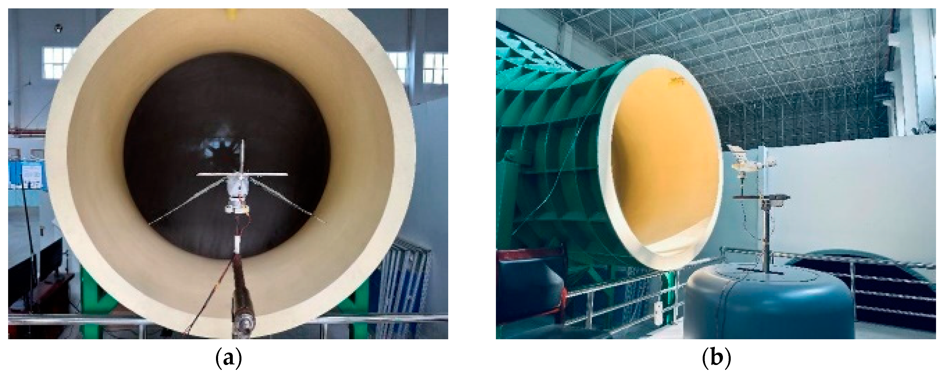
Figure 15.
Variation of lift and thrust with angle of attack at different throttle settings.
Figure 15.
Variation of lift and thrust with angle of attack at different throttle settings.
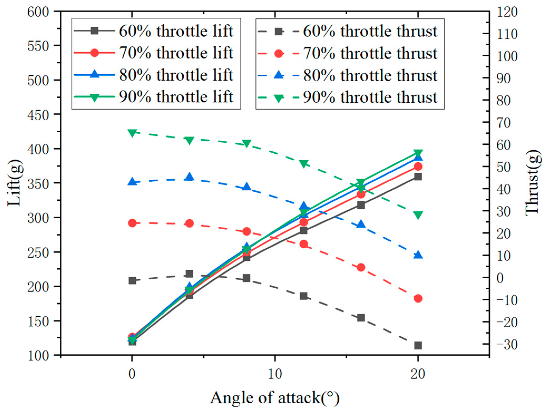
Figure 16.
Variation of angle of attack at zero thrust and corresponding lift with flapping frequency.
Figure 16.
Variation of angle of attack at zero thrust and corresponding lift with flapping frequency.
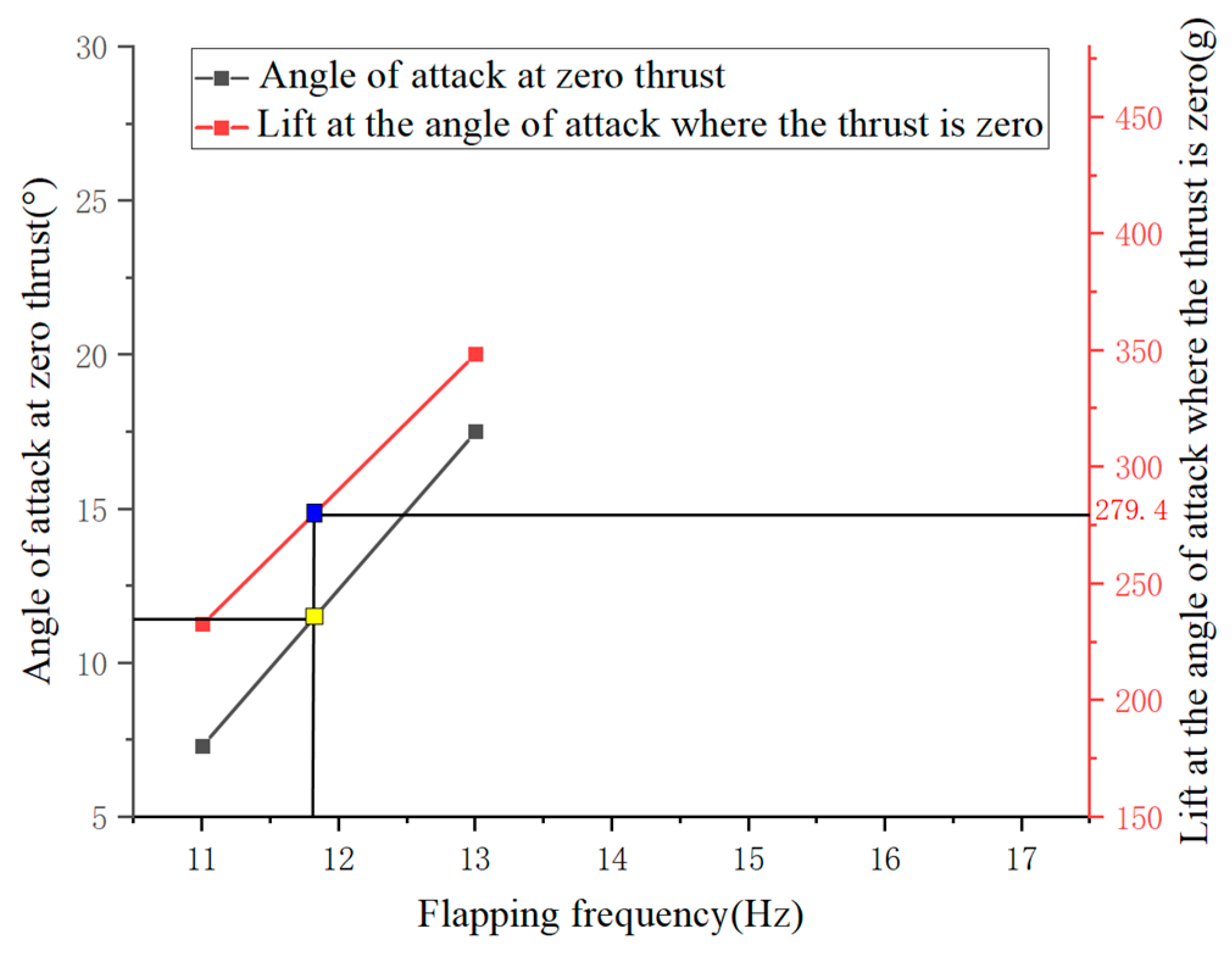
Figure 17.
At a wind speed of 10 m/s, the variation of lift with flapping frequency is studied for different motors and different angles of attack. (a) The variation of lift with angle of attack is studied for the GTS V3 2104 motor at different flapping frequencies. (b) The variation of lift with angle of attack is studied for the Aeolus 2105.5 motor at different flapping frequencies.
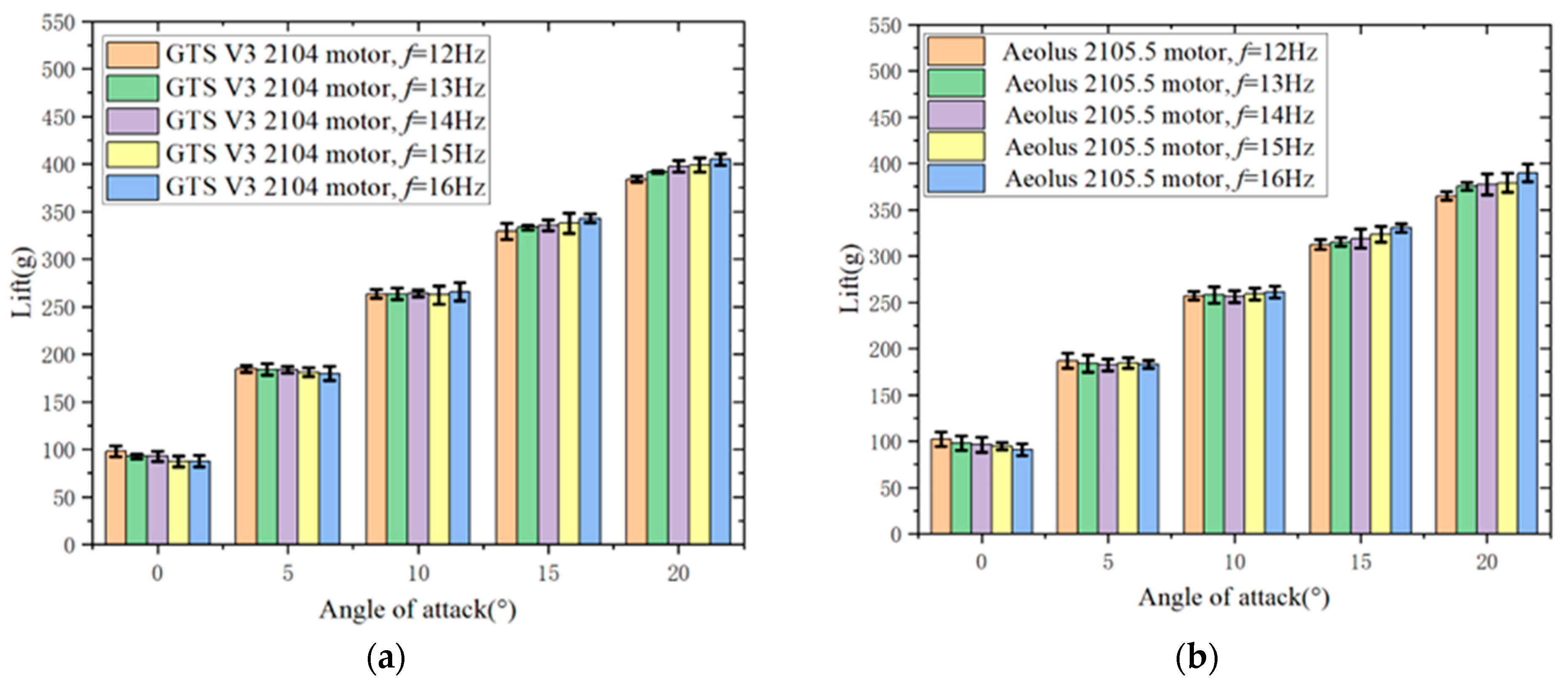
Figure 18.
At a wind speed of 10 m/s, the variation of thrust with flapping frequency is studied for different motors and different angles of attack. (a) The variation of thrust with angle of attack is studied for the GTS V3 2104 motor at different flapping frequencies. (b) The variation of thrust with angle of attack is studied for the Aeolus 2105.5 motor at different flapping frequencies.
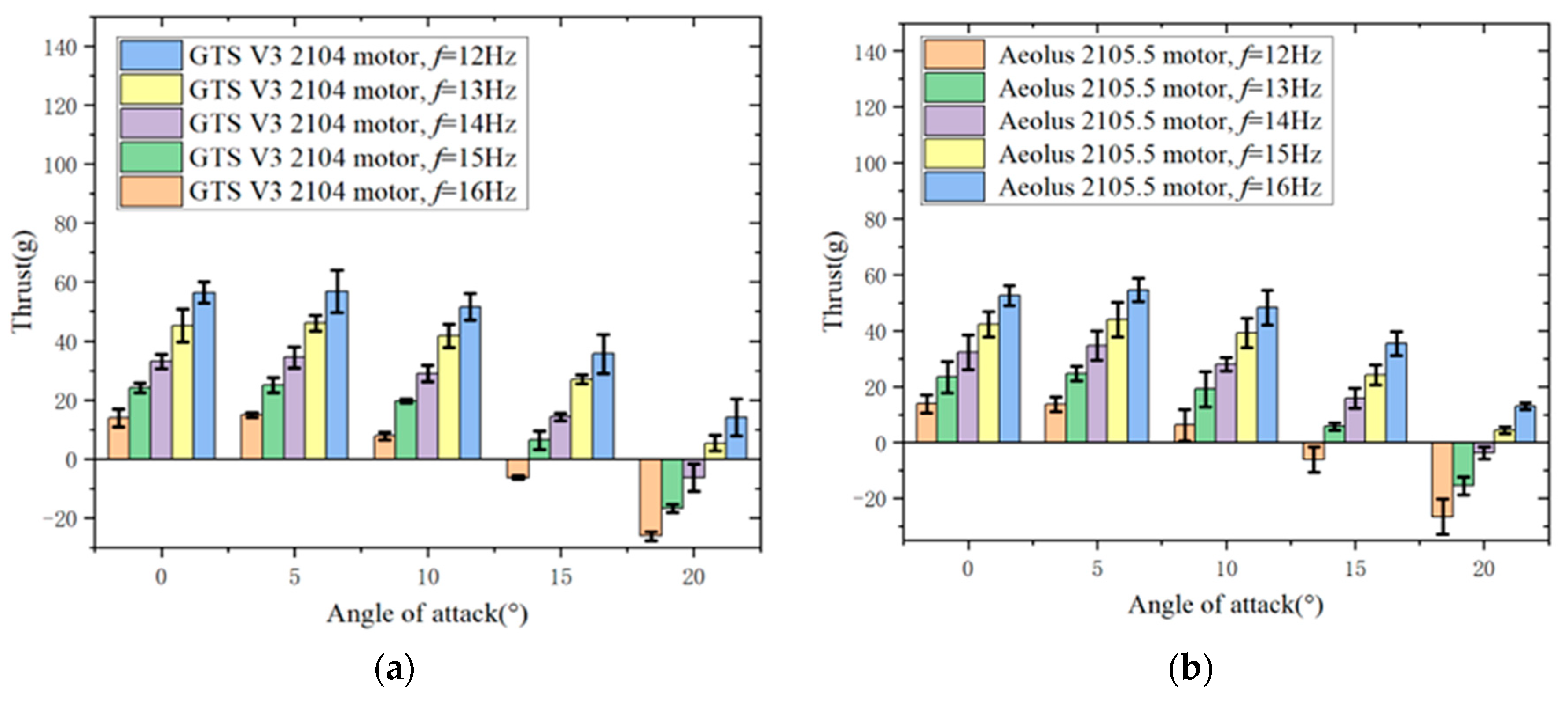
Figure 19.
The variation of lift and thrust with angle of attack is analyzed at a wind speed of 10 m/s for different motors and flapping frequencies. (a) The variation of lift with angle of attack is analyzed at a wind speed of 10 m/s for different motors and flapping frequencies. (b) The variation of thrust with angle of attack is analyzed at a wind speed of 10m/s for different motors and flapping frequencies.
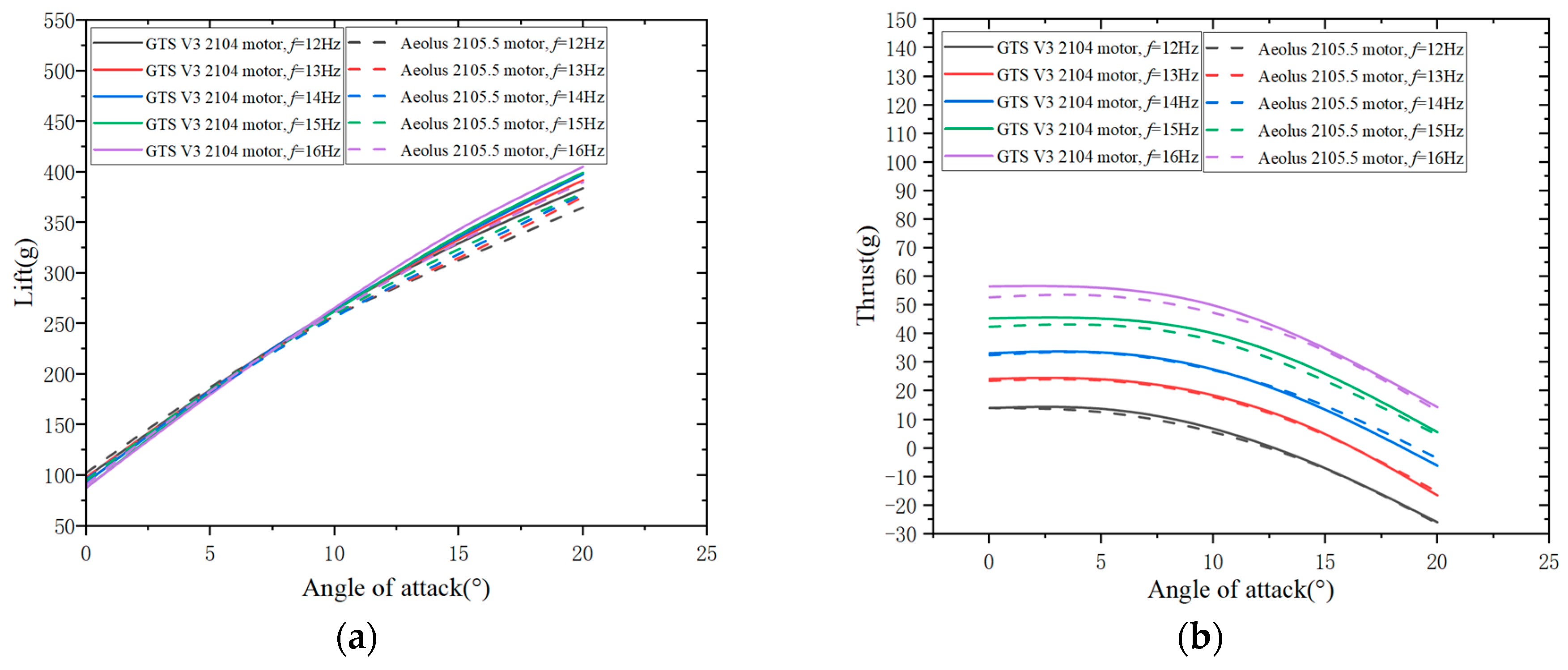
Figure 20.
At a wind speed of 12.5 m/s, the variation of lift with flapping frequency is studied for different motors and different angles of attack. (a) The variation of lift with angle of attack is studied for the GTS V3 2104 motor at different flapping frequencies. (b) The variation of lift with angle of attack is studied for the Aeolus 2105.5 motor at different flapping frequencies.
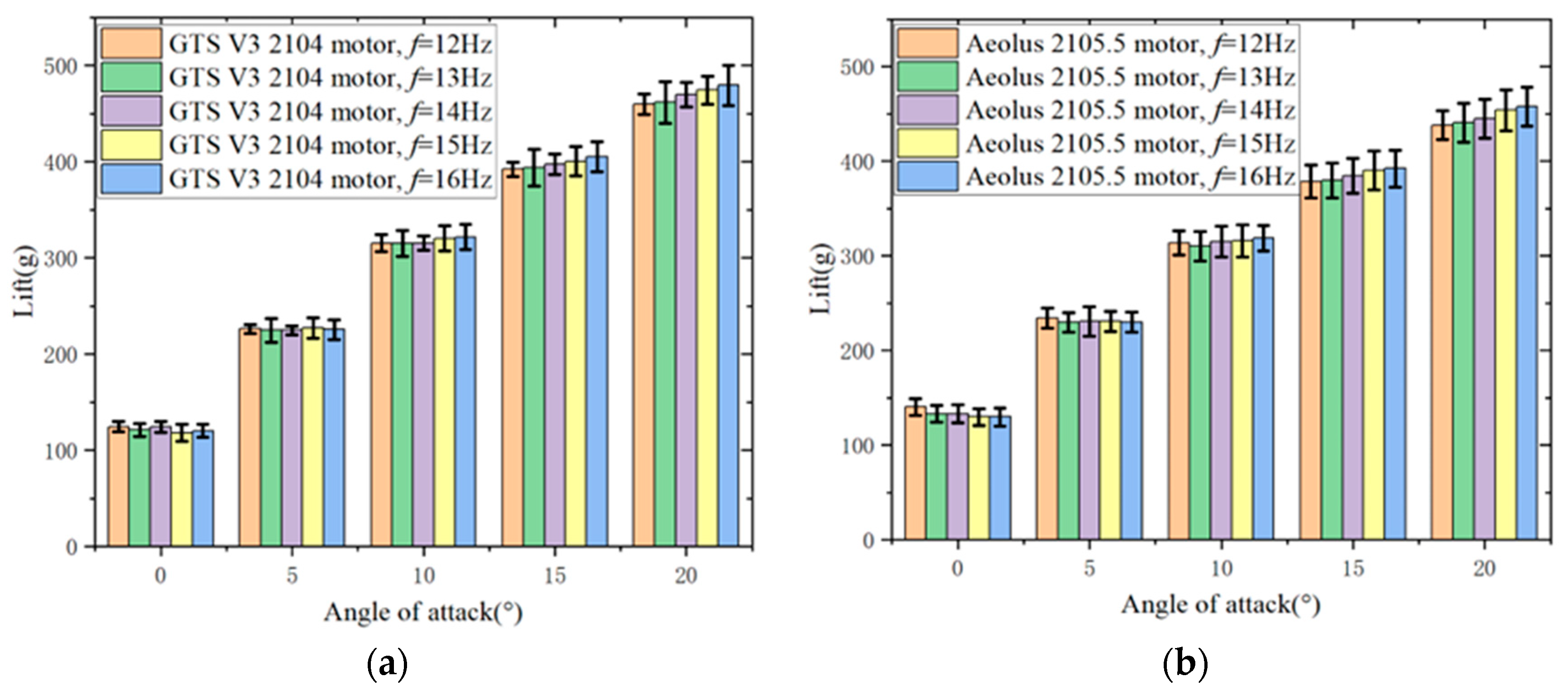
Figure 21.
At a wind speed of 12.5 m/s, the variation of thrust with flapping frequency is studied for different motors and different angles of attack. (a) The variation of thrust with angle of attack is studied for the GTS V3 2104 motor at different flapping frequencies. (b) The variation of thrust with angle of attack is studied for the Aeolus 2105.5 motor at different flapping frequencies.
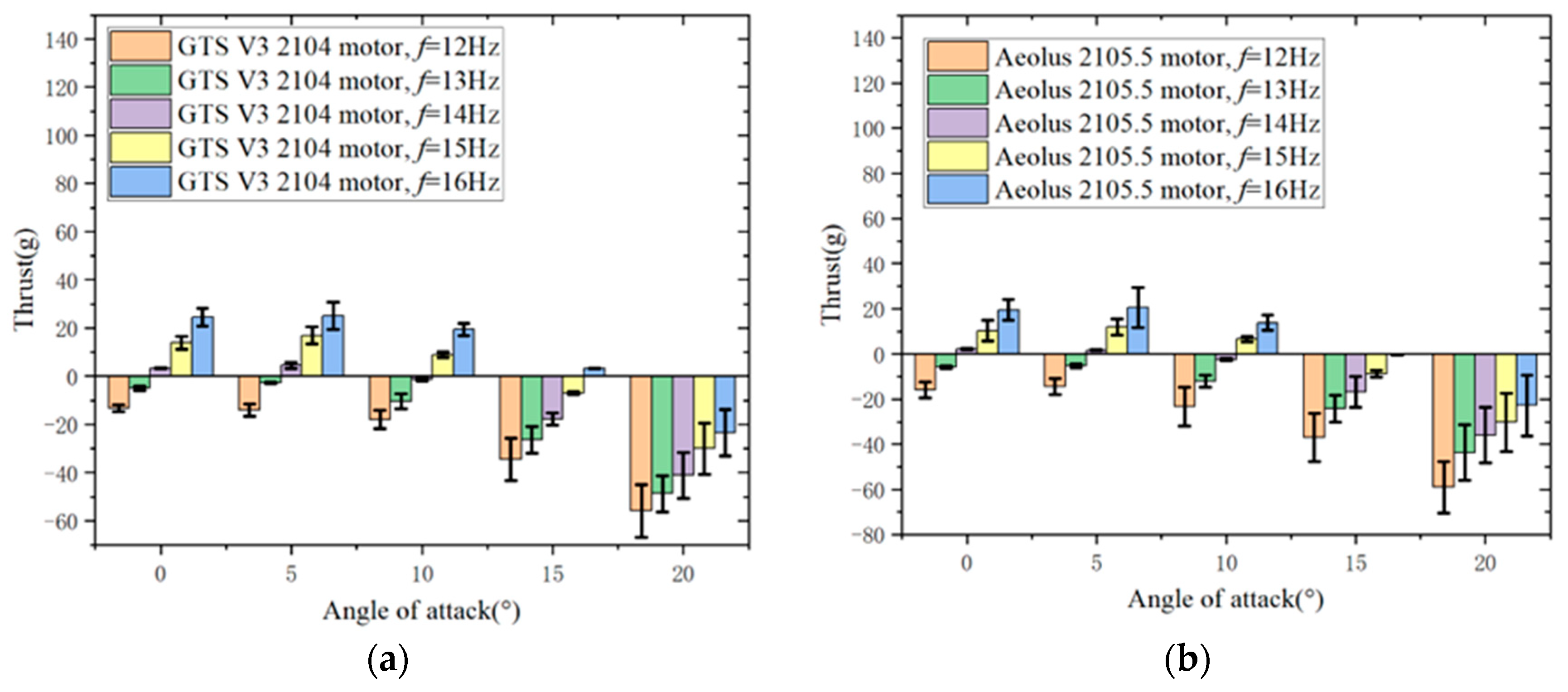
Figure 22.
The curves depicting the variation of lift and thrust with angle of attack are analyzed at a wind speed of 12.5 m/s for different motors and flapping frequencies. (a) The variation of lift with angle of attack is analyzed at a wind speed of 10 m/s for different motors and flapping frequencies. (b) The variation of thrust with angle of attack is analyzed at a wind speed of 10m/s for different motors and flapping frequencies.
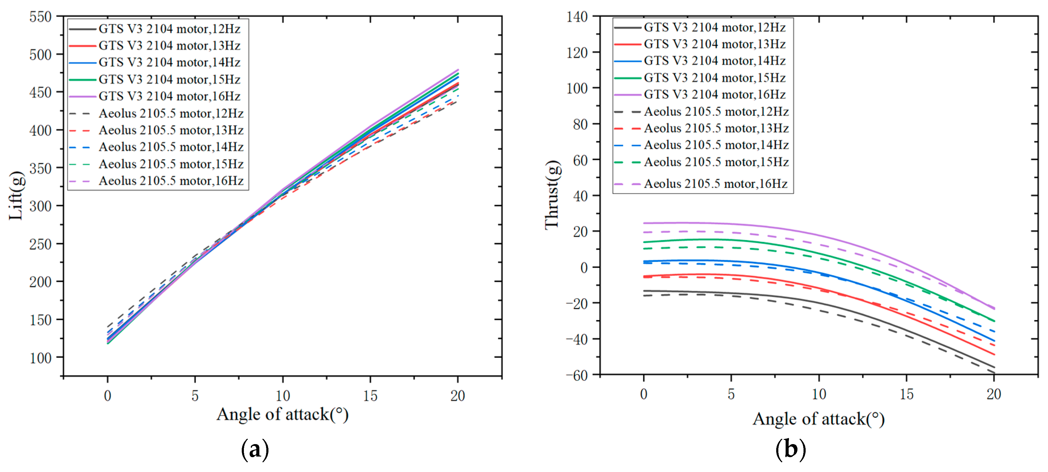
Figure 23.
The curves depicting the variation of lift and thrust with angle of attack are analyzed for the GTS V3 2104 motor at different wind speeds and flapping frequencies. (a) The variation of lift with angle of attack is studied at different wind speeds and flapping frequencies. (b) The variation of thrust with angle of attack is studied at different wind speeds and flapping frequencies.
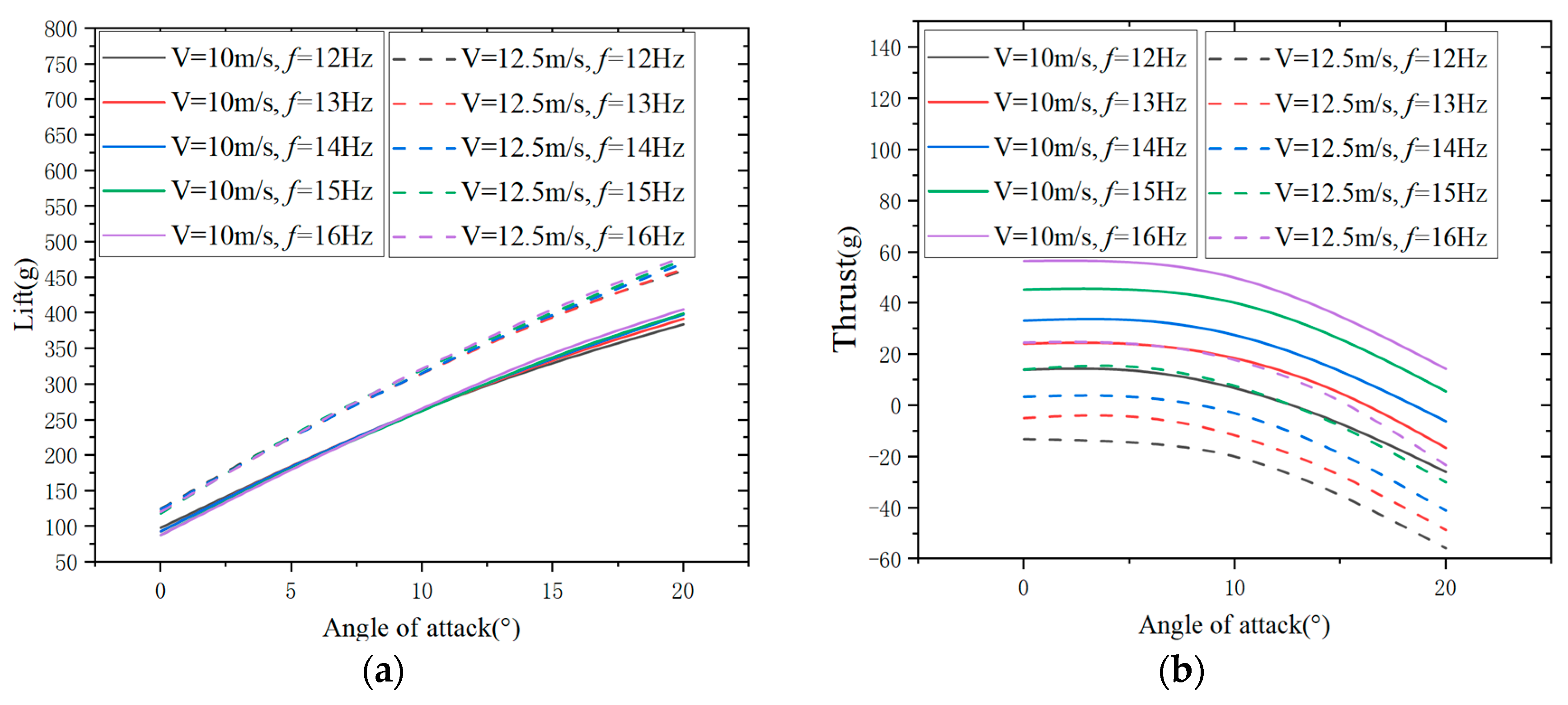
Figure 24.
The curves depicting the variation of lift and thrust with angle of attack are analyzed for the Aeolus 2105.5 motor at different wind speeds and flapping frequencies. (a) The variation of lift with angle of attack is studied at different wind speeds and flapping frequencies. (b) The variation of thrust with angle of attack is studied at different wind speeds and flapping frequencies.
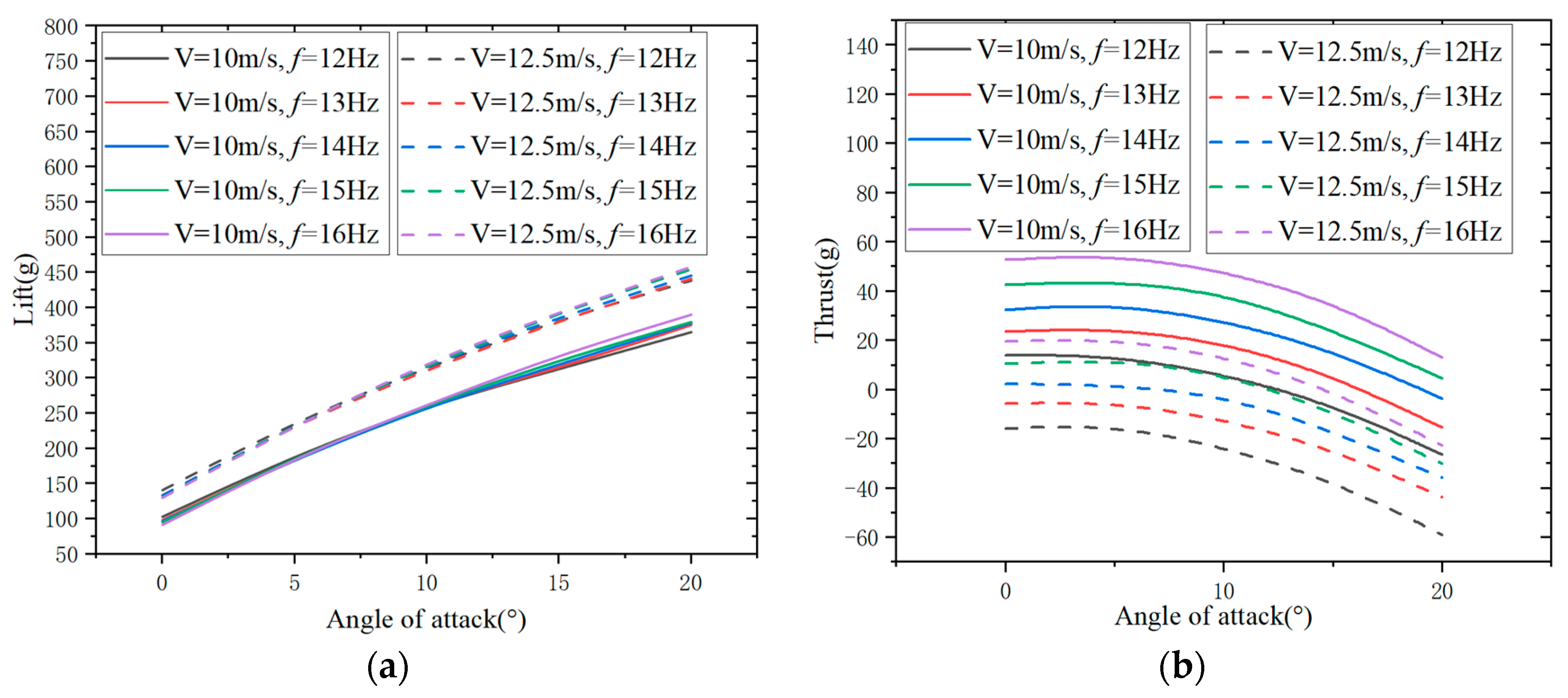
Figure 25.
The power output of the GTS V3 2104 motor varies with angle of attack at different wind speeds and flapping frequencies.
Figure 25.
The power output of the GTS V3 2104 motor varies with angle of attack at different wind speeds and flapping frequencies.
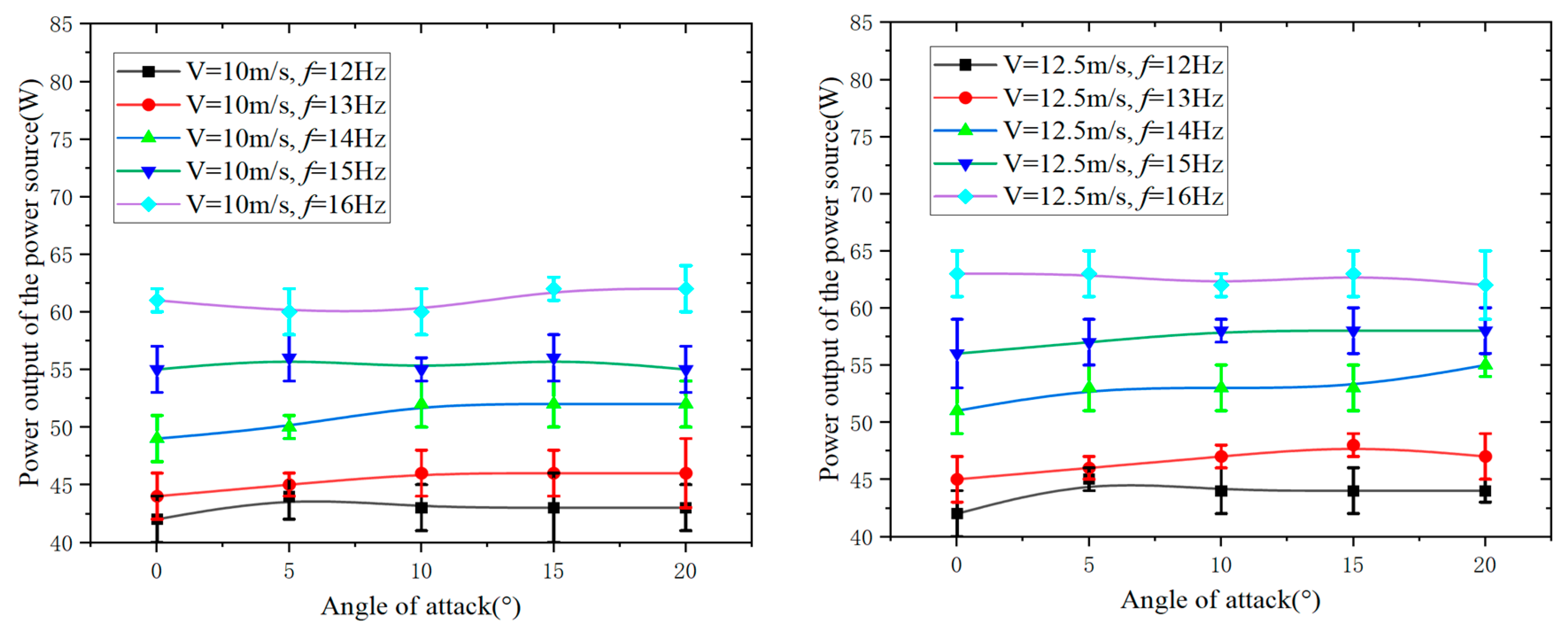
Figure 26.
The power output of the Aeolus 2105.5 motor varies with angle of attack at different wind speeds and flapping frequencies.
Figure 26.
The power output of the Aeolus 2105.5 motor varies with angle of attack at different wind speeds and flapping frequencies.
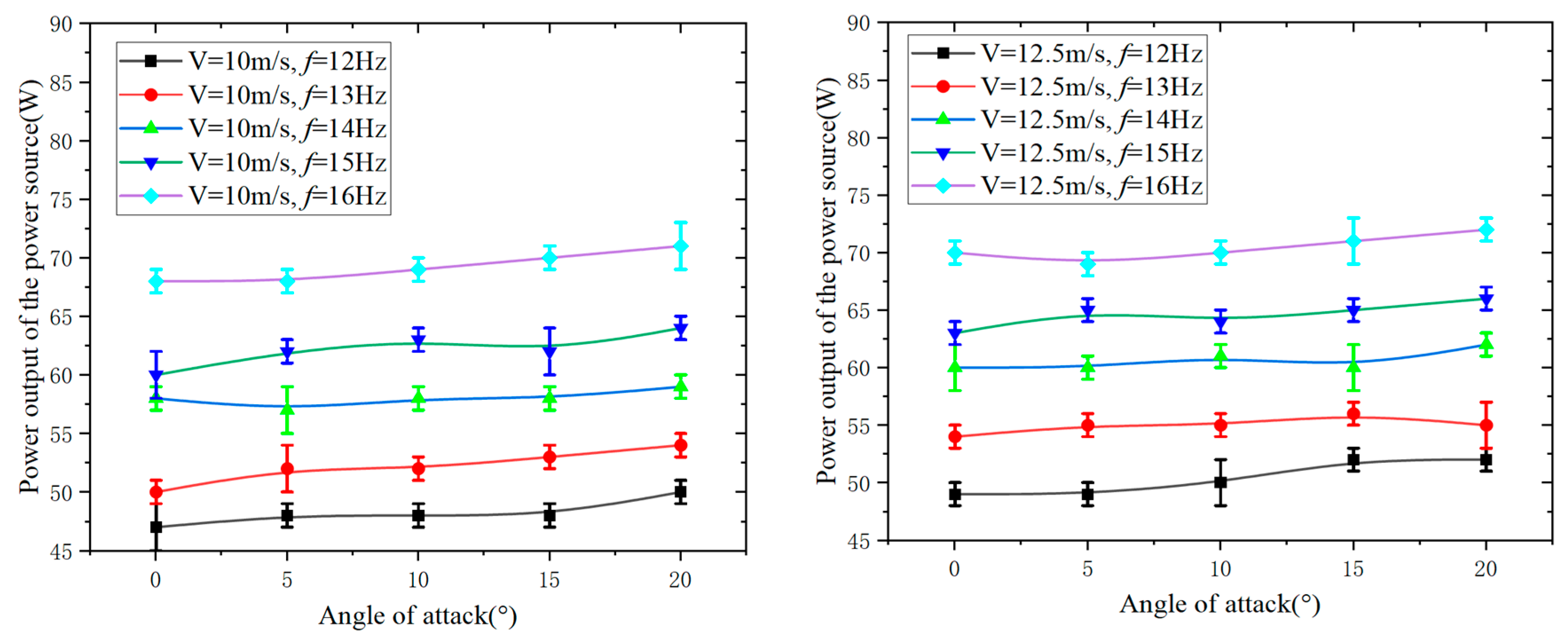
Figure 27.
Curves depicting the variation of input power with angle of attack for the GTS V3 2104 motor flight test prototype at different wind speeds and flapping frequencies.
Figure 27.
Curves depicting the variation of input power with angle of attack for the GTS V3 2104 motor flight test prototype at different wind speeds and flapping frequencies.
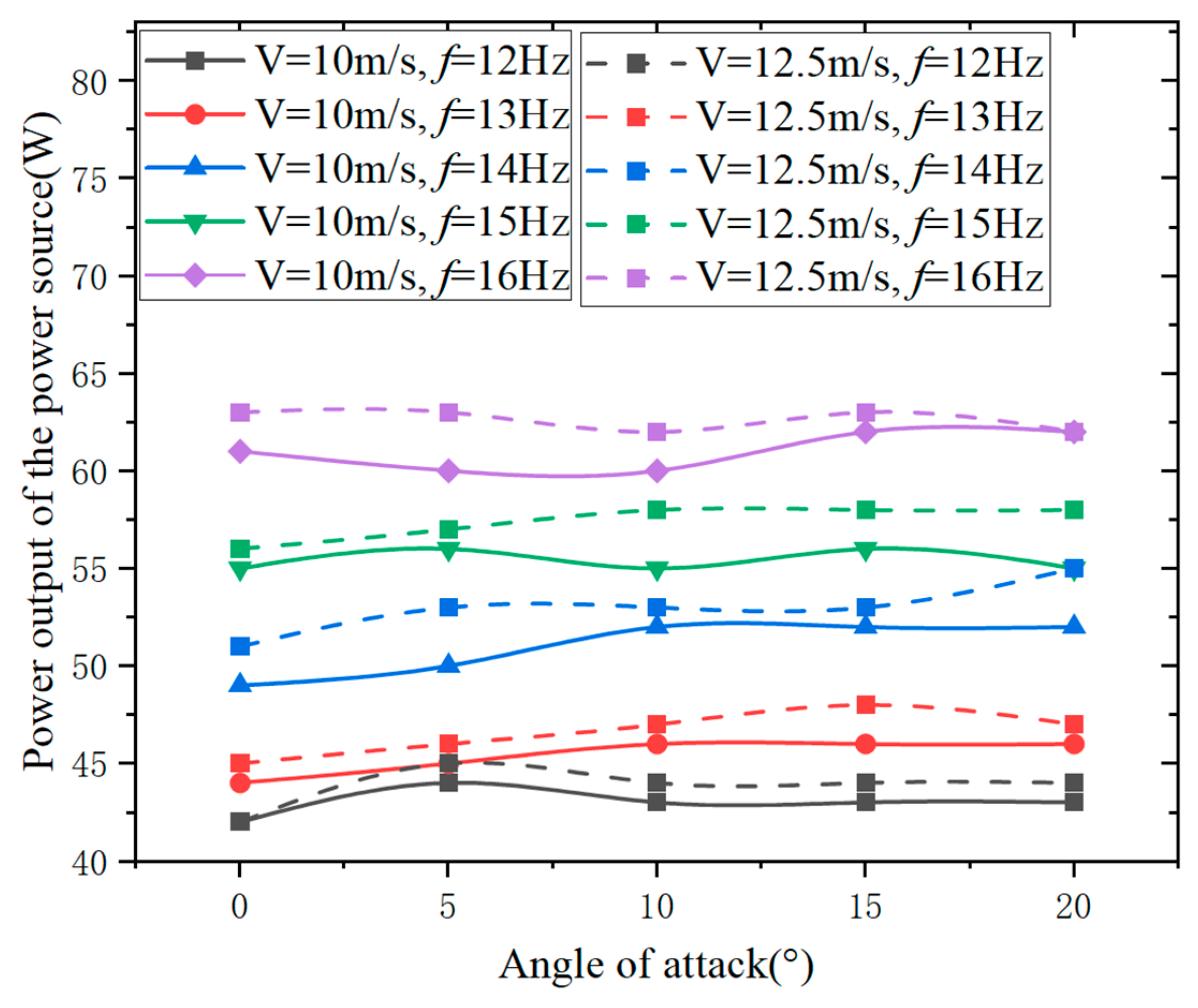
Figure 28.
Curves depicting the variation of input power with angle of attack for the Aeolus 2105.5 motor flight test prototype at different wind speeds and flapping frequencies.
Figure 28.
Curves depicting the variation of input power with angle of attack for the Aeolus 2105.5 motor flight test prototype at different wind speeds and flapping frequencies.
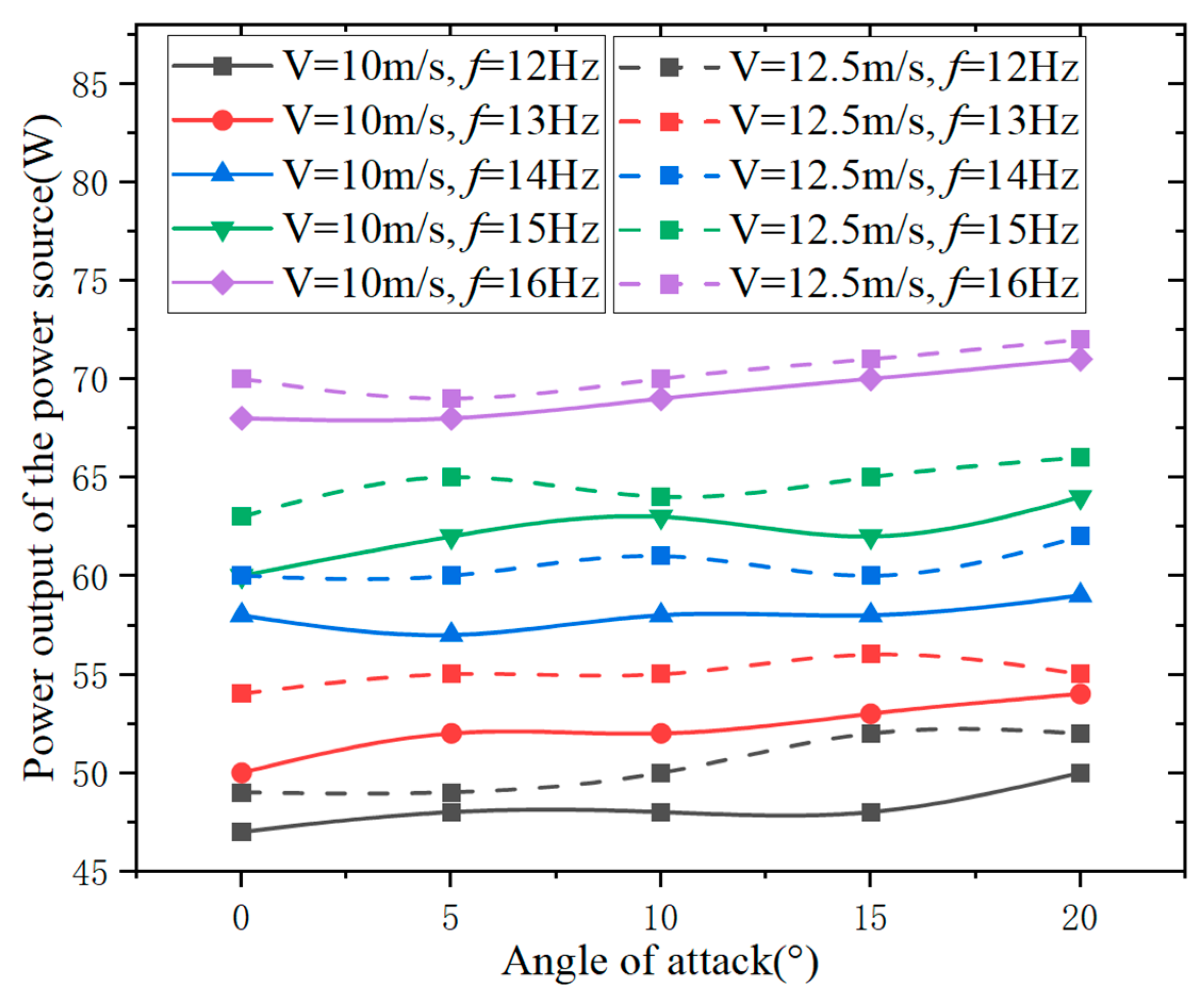
Figure 29.
Curve depicting the variation of the angle of attack at zero thrust and the corresponding lift with respect to the flapping frequency at a wind speed of 12.5 m/s.
Figure 29.
Curve depicting the variation of the angle of attack at zero thrust and the corresponding lift with respect to the flapping frequency at a wind speed of 12.5 m/s.
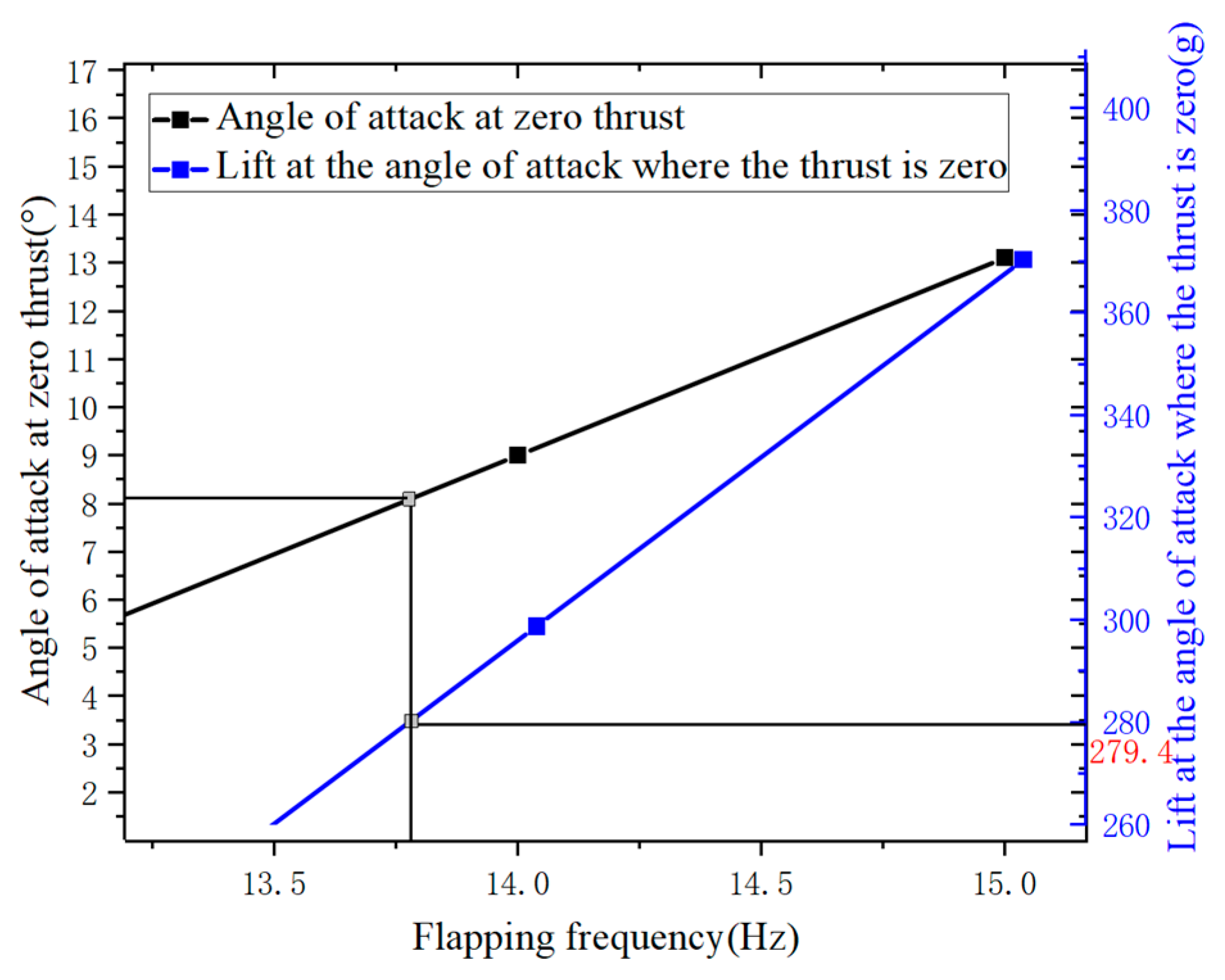
Figure 30.
Curve depicting the variation of the angle of attack at zero thrust and the corresponding lift with respect to the flapping frequency at a wind speed of 10 m/s.
Figure 30.
Curve depicting the variation of the angle of attack at zero thrust and the corresponding lift with respect to the flapping frequency at a wind speed of 10 m/s.
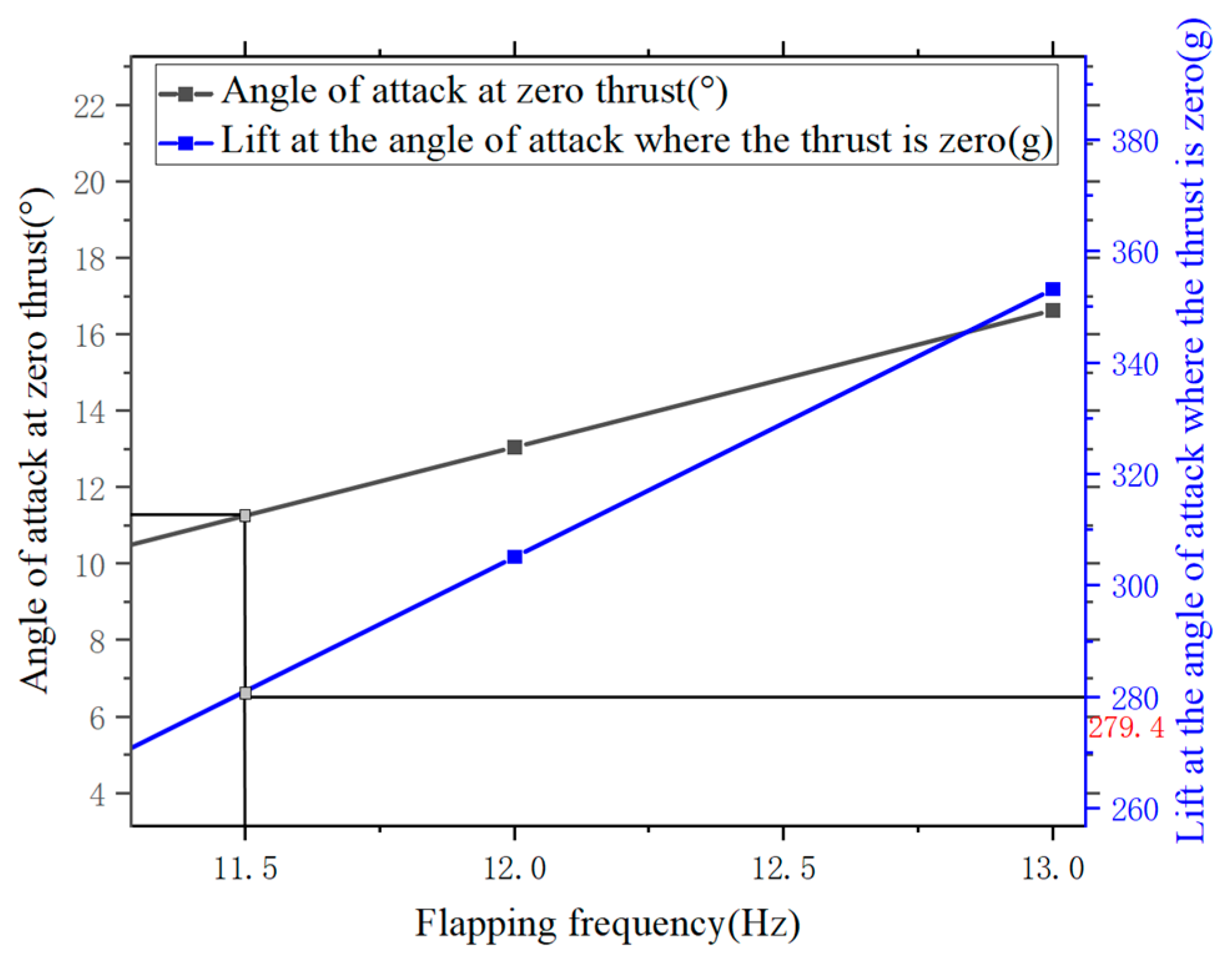
Figure 31.
Curves depicting the variation of trimmed flapping frequency and angle of attack with respect to velocity.
Figure 31.
Curves depicting the variation of trimmed flapping frequency and angle of attack with respect to velocity.
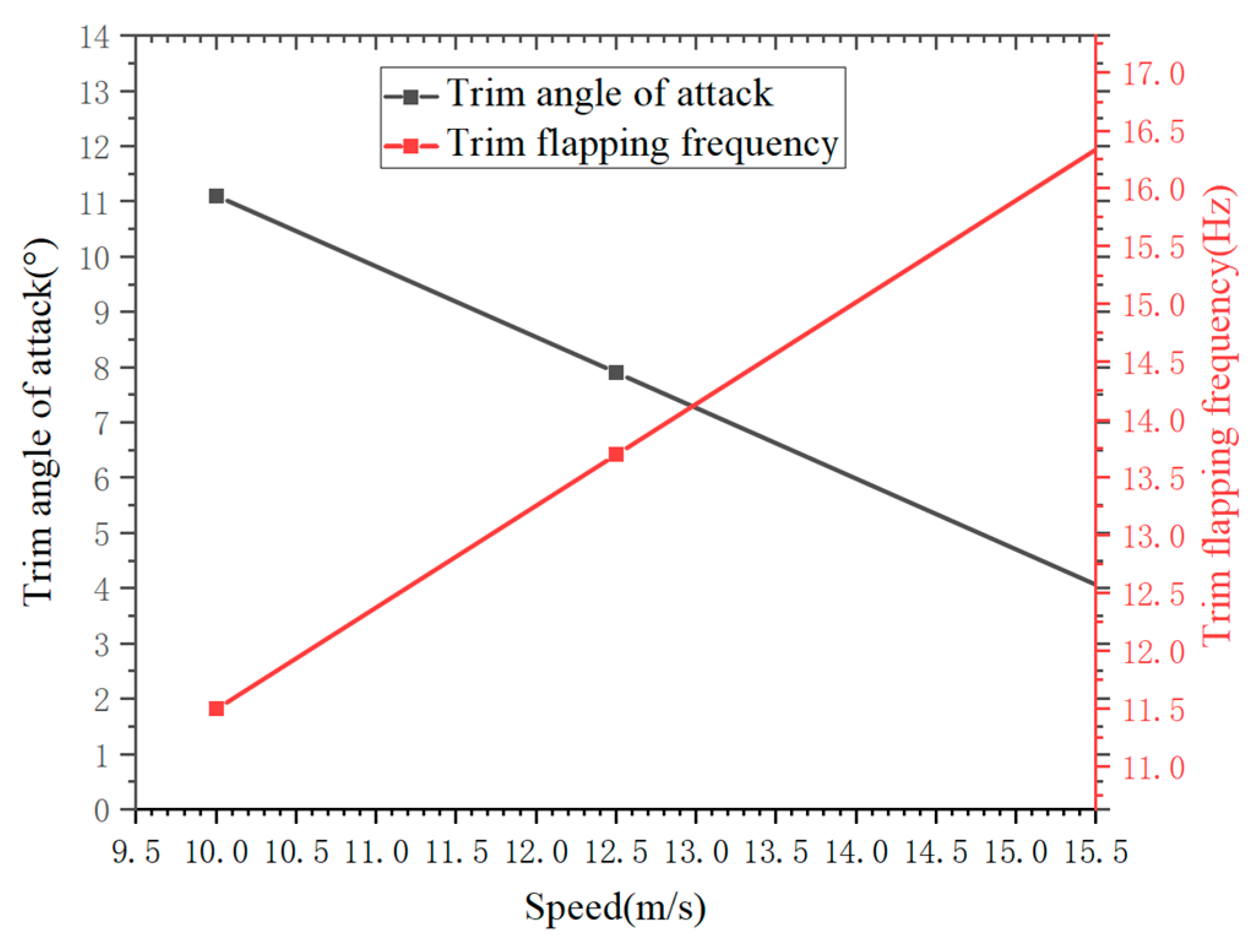
Figure 32.
Initial pitch angle of the aircraft.
Figure 32.
Initial pitch angle of the aircraft.
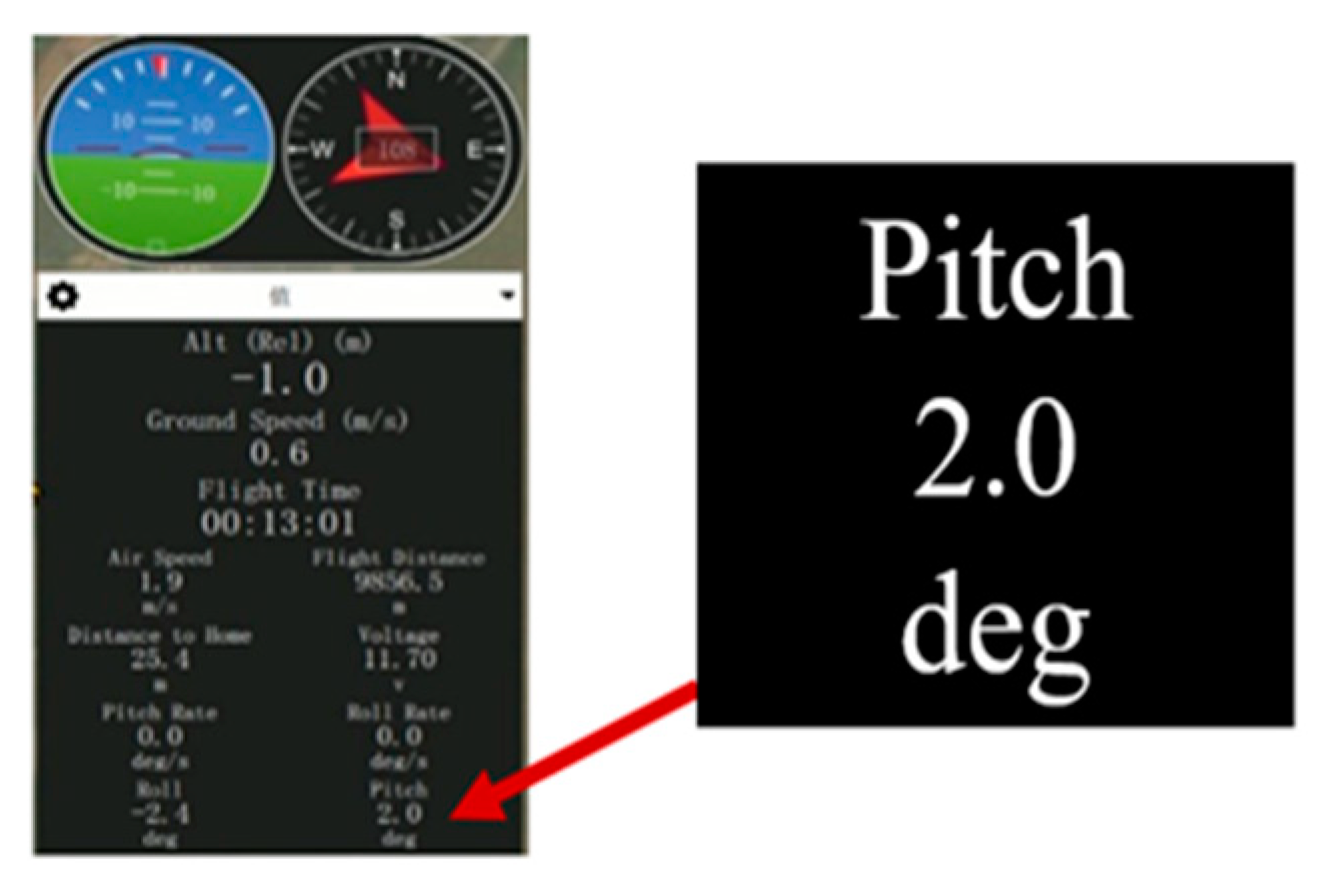
Figure 33.
(a) Variation of pitch angle, velocity, and altitude of the aircraft over time during the interval of 180 s~181 s. (b) Variation of pitch angle, velocity, and altitude of the aircraft over time during the interval of 184 s~185 s. (c) Variation of pitch angle, velocity, and altitude of the aircraft over time during the interval of 262 s~263 s.
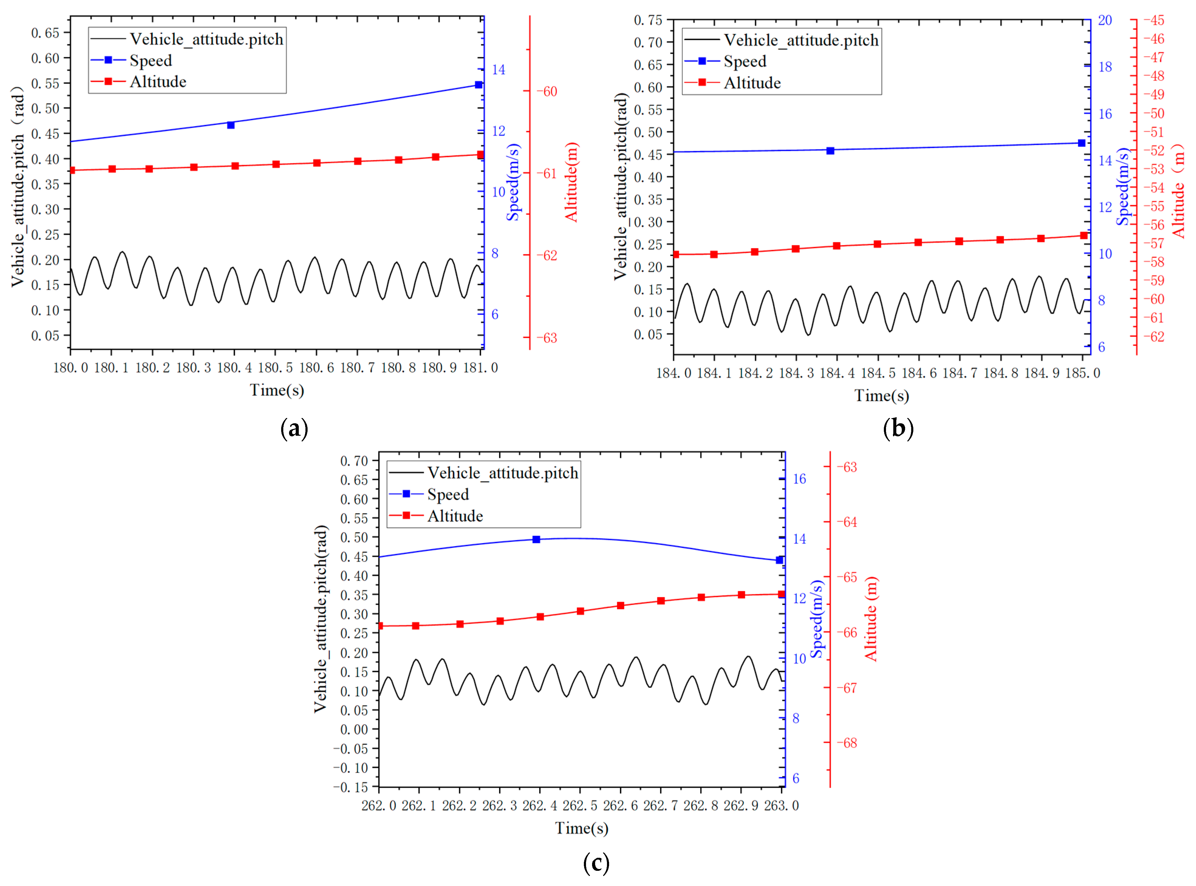
Figure 34.
Flight spectrum plot.
Figure 34.
Flight spectrum plot.
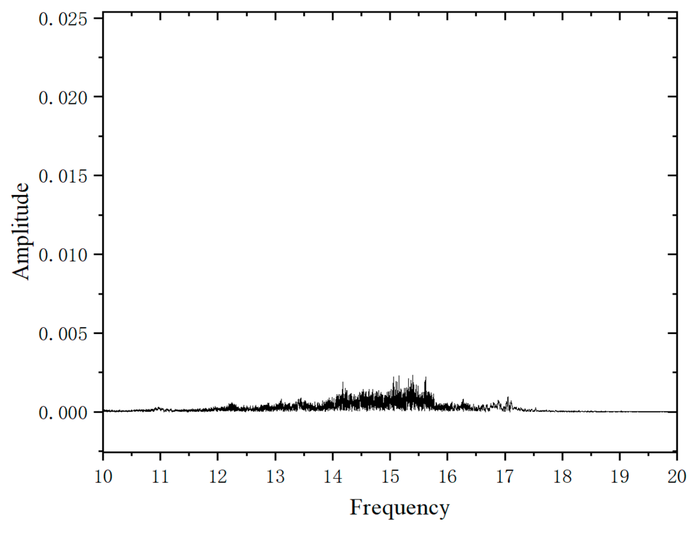
Figure 35.
Variation of aircraft pitch angle over time during the flight phase.
Figure 35.
Variation of aircraft pitch angle over time during the flight phase.
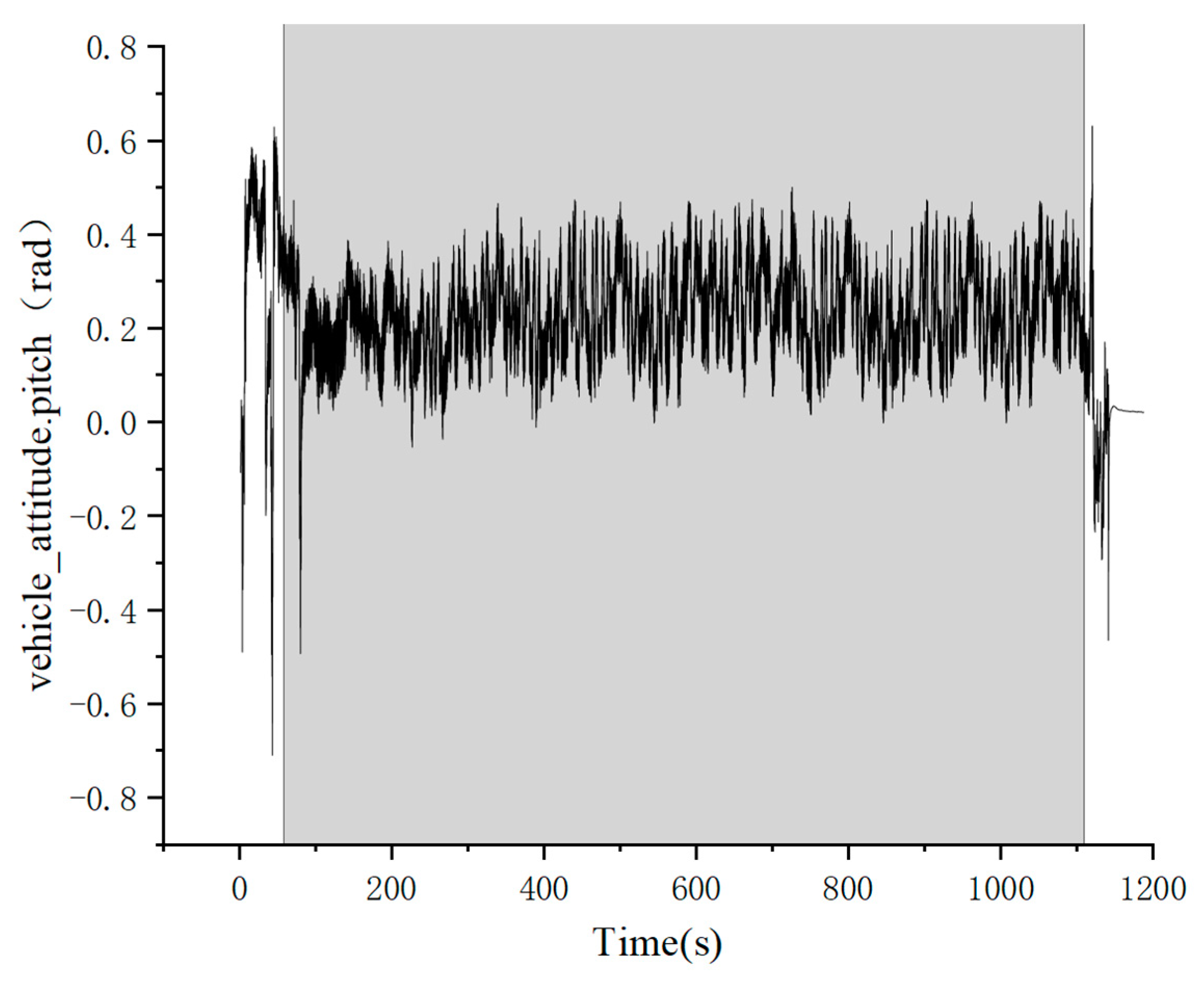
Figure 36.
Curve depicting the variation of aircraft speed with flight time.
Figure 36.
Curve depicting the variation of aircraft speed with flight time.
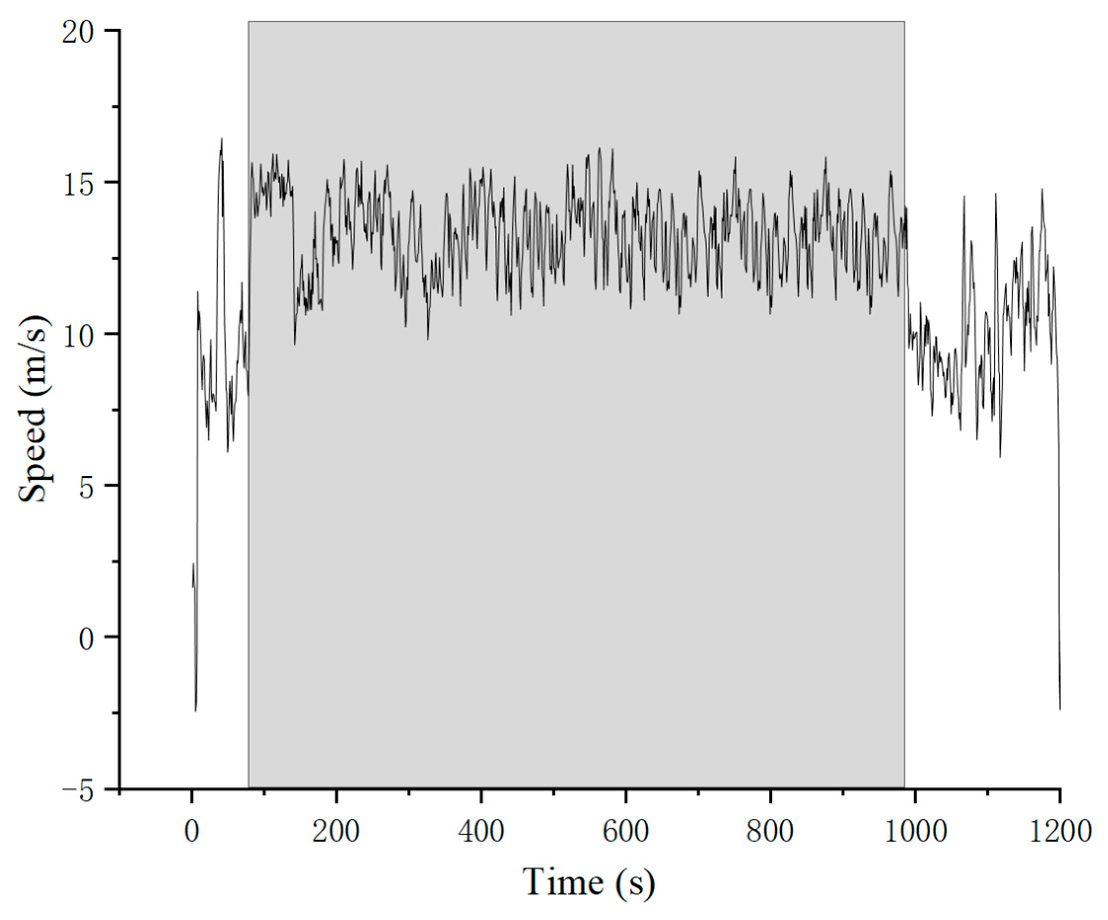
Table 1.
Comparison between the flight speeds of bio-inspired flapping-wing aircraft and real organisms.
Table 1.
Comparison between the flight speeds of bio-inspired flapping-wing aircraft and real organisms.
| Bio-Inspired Aircraft | Flight Speed (m/s) | Real Organism Flight Speed (m/s) | Bio-Inspired Aircraft Image |
|---|---|---|---|
| RoboBee | 1 | 6 |  |
| Nano Hummingbird | 4.7 | 8.3 |  |
| SmartBird | 7 | 14 |  |
| Dove | 10 | 16 |  |
Table 2.
Main Parameters of “Dove” Aircraft.
Table 2.
Main Parameters of “Dove” Aircraft.
| Parameter | Value |
|---|---|
| Weight/g | 230~280 |
| Wingspan/cm | 60 |
| Cruising Speed/(m/s) | 10 |
| Flapping Frequency/Hz | 10 |
| Maximum Flight Time/min | 185 |
Table 3.
Parameters of the three motors.
Table 3.
Parameters of the three motors.
| Motor Model | KV Value (RPM/V) | No-Load Current (A) | Resistance (Ω) | Weight (g) |
|---|---|---|---|---|
| MN1804 | 2400 | 0.49 | 0.78 | 16 |
| Aeolus 2105.5 | 3600 | 1.4 | 0.07 | 21 |
| GTS V3 2104 | 3000 | 0.9 | 0.11 | 16 |
Table 4.
Motor efficiency and gear ratio with a flapping frequency of 15 Hz of MN1804 at different voltages.
Table 4.
Motor efficiency and gear ratio with a flapping frequency of 15 Hz of MN1804 at different voltages.
| Voltage (V) | Output Torque (N∙m) | Output Speed (rad/s) | Current (A) | Motor Efficiency (%) | Gear Ratio |
|---|---|---|---|---|---|
| 13.05 | 4.46 | 65.3 | |||
| 12.38 | 4.95 | 62.0 | |||
| 11.67 | 5.82 | 56.0 | |||
| 11.30 | 7.00 | 48.2 | |||
| 10.11 | —— | —— | —— | —— | —— |
Table 5.
Motor efficiency and gear ratio with a flapping frequency of 15 Hz of Aeolus 2105.5 at different voltages.
Table 5.
Motor efficiency and gear ratio with a flapping frequency of 15 Hz of Aeolus 2105.5 at different voltages.
| Voltage (V) | Output Torque (N∙m) | Output Speed (rad/s) | Current (A) | Motor Efficiency (%) | Gear Ratio |
|---|---|---|---|---|---|
| 13.05 | 4.38 | 66.5 | |||
| 12.38 | 4.55 | 67.5 | |||
| 11.67 | 4.75 | 68.5 | |||
| 10.92 | 5.00 | 69.7 | |||
| 10.11 |
Table 6.
Motor efficiency and gear ratio with a flapping frequency of 15 Hz of GTS V3 2104 at different voltages.
Table 6.
Motor efficiency and gear ratio with a flapping frequency of 15 Hz of GTS V3 2104 at different voltages.
| Voltage (V) | Output Torque (N∙m) | Output Speed (rad/s) | Current (A) | Motor Efficiency (%) | Gear Ratio |
|---|---|---|---|---|---|
| 13.05 | 3.91 | 74.5 | |||
| 12.38 | 4.09 | 75.1 | |||
| 11.67 | 4.30 | 75.8 | |||
| 10.92 | 4.55 | 76.5 | |||
| 10.11 |
Table 7.
Flapping frequencies of different motors at different throttle settings.
Table 7.
Flapping frequencies of different motors at different throttle settings.
| Throttle (%) | GTS V3 2104 Motor Flight Test Prototype Flapping Frequency (Hz) |
Aeolus 2105.5 Motor Flight Test Prototype Flapping Frequency (Hz) |
|---|---|---|
| 60 | 11 | 13 |
| 70 | 13 | 15 |
| 80 | 15 | 17 |
| 90 | 17 | 19 |
| 100 | 19 | 21 |
Table 8.
Wind tunnel experimental design variables.
Table 8.
Wind tunnel experimental design variables.
| Parameters | Values |
|---|---|
| Motor Type | GTS V3 2104, Aeolus 2105.5 |
| Angle of Attack | 0°, 5°, 10°, 15°, 20° |
| Flapping Frequency | 12 Hz, 13 Hz, 14 Hz, 15 Hz, 16 Hz |
| Wind Speed | 10 m/s, 12.5 m/s |
Table 9.
Pitch angle, flight speed, and flapping frequency of the aircraft in different time intervals.
Table 9.
Pitch angle, flight speed, and flapping frequency of the aircraft in different time intervals.
| Time (s) | Pitch Angle (°) | Average Flight Speed (m/s) | Flapping Frequency (Hz) |
|---|---|---|---|
| 180~181 | 7.3 | 12.8 | 14.9 |
| 184~185 | 4.9 | 14.6 | 14.5 |
| 262~263 | 7.5 | 13.6 | 14.5 |
Table 10.
Trimmed pitch angle, flapping frequency, and errors for different time intervals in wind tunnel experiments.
Table 10.
Trimmed pitch angle, flapping frequency, and errors for different time intervals in wind tunnel experiments.
| Time (s) | Pitch Angle (°) |
Average Flight Speed (m/s) | Flapping Frequency (Hz) |
Trimmed Pitch Angle from Wind Tunnel (°) | Trimmed Flapping Frequency from Wind Tunnel (Hz) |
Pitch Angle Error (%) |
Flapping Frequency Error (%) |
|---|---|---|---|---|---|---|---|
| 180~181 | 7.3 | 12.8 | 14.9 | 7.5 | 14.0 | 3 | 7 |
| 184~185 | 4.9 | 14.6 | 14.5 | 5.2 | 15.5 | 6 | 6 |
| 262~263 | 7.5 | 13.6 | 14.5 | 6.5 | 14.7 | 15 | 1 |
[ad_2]