Surrogate Optimal Fractional Control for Constrained Operational Service of UAV Systems
[ad_1]
Author Contributions
Conceptualization, A.M.M. and M.B.A.; methodology, A.M.M., M.B.A. and K.M.M.; software, A.M.M., M.B.A. and K.M.M.; validation, A.M.M. and M.B.A.; investigation, M.M. (Mohammed Moness) and M.M. (Moataz Mohamed); resources, M.M. (Mohammed Moness) and M.M. (Moataz Mohamed); writing—original draft preparation, K.M.M.; writing—review and editing, A.M.M., M.B.A. and M.M. (Moataz Mohamed); supervision, M.M. (Mohammed Moness) and M.M. (Moataz Mohamed). All authors have read and agreed to the published version of the manuscript.
Figure 1.
Challenge complexity of intersecting decision levels and constraints of UAV operation.
Figure 1.
Challenge complexity of intersecting decision levels and constraints of UAV operation.
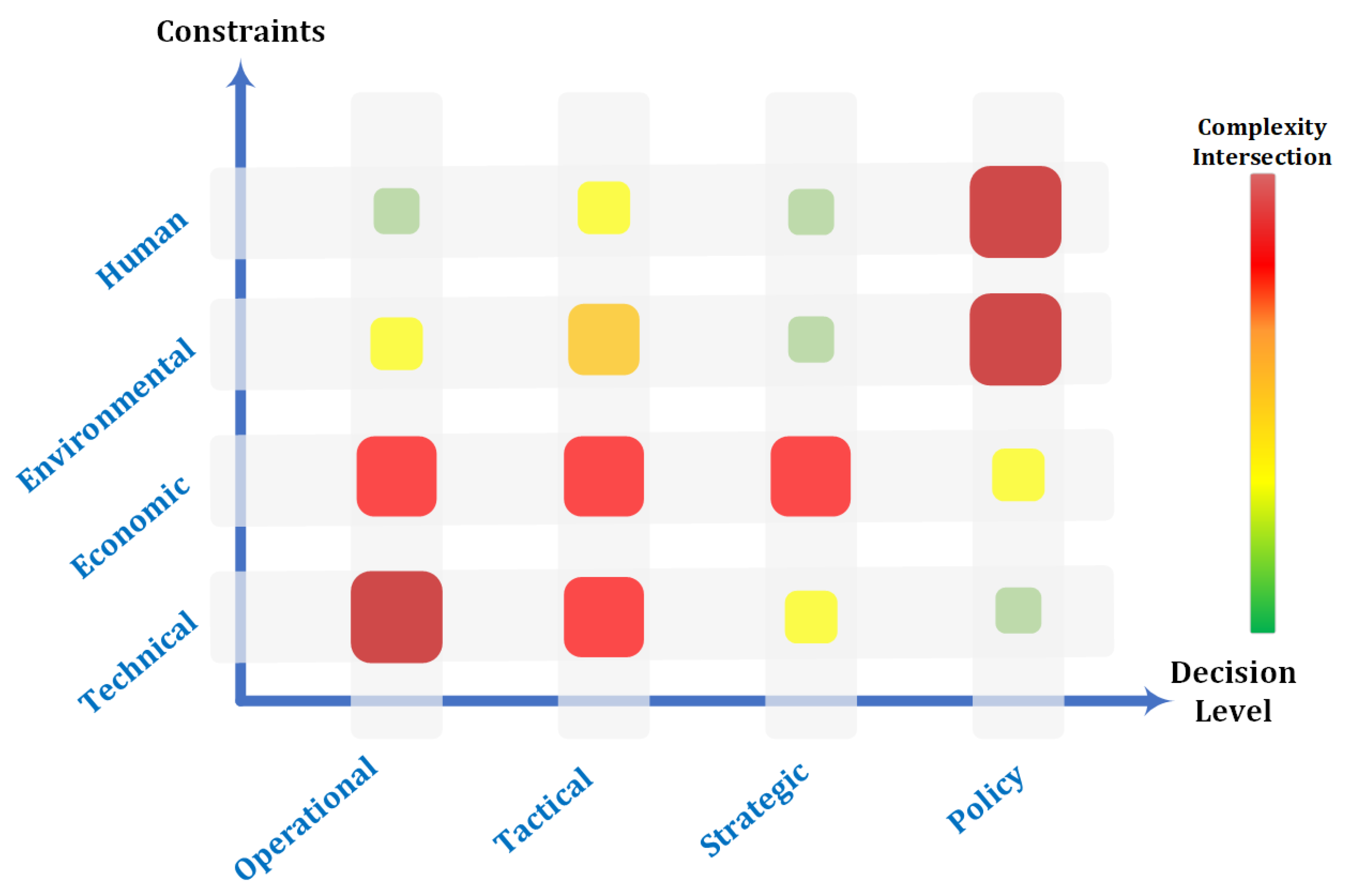
Figure 2.
Design optimization criterion with its reflection in a set of operational requirements.
Figure 2.
Design optimization criterion with its reflection in a set of operational requirements.
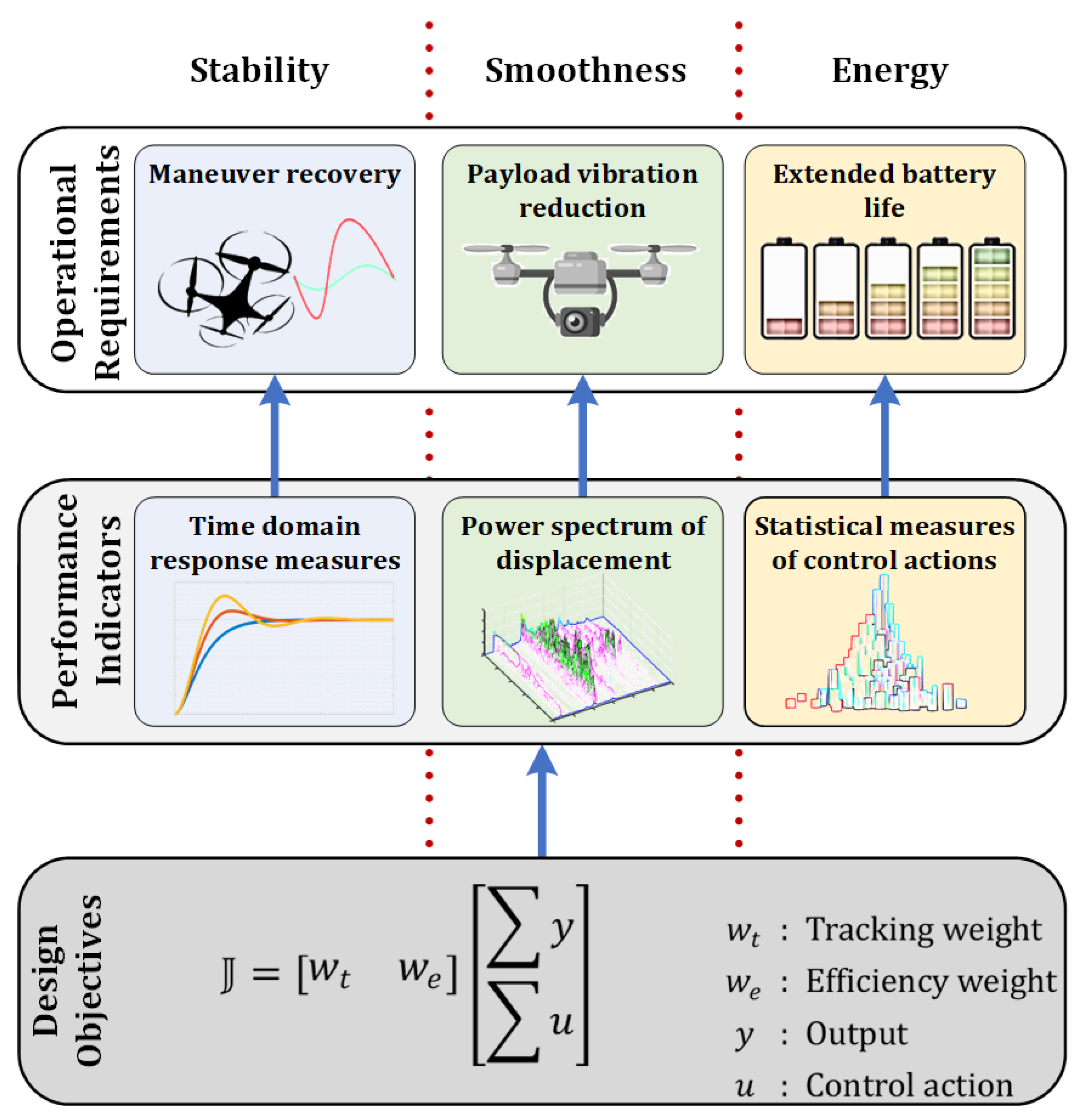
Figure 3.
Frequency responses for a sample of FOPID with unity gains.
Figure 3.
Frequency responses for a sample of FOPID with unity gains.
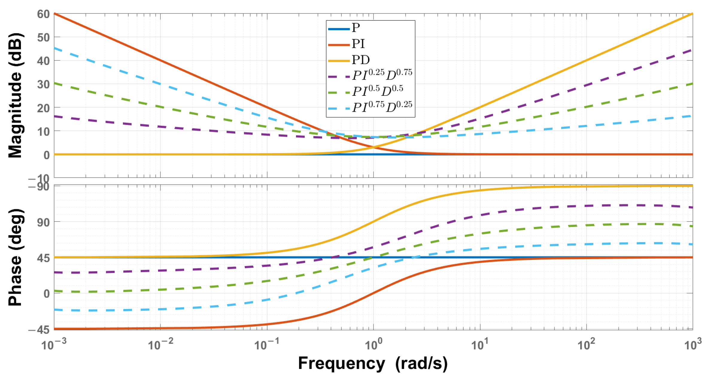
Figure 4.
The quadrotor model frames.
Figure 4.
The quadrotor model frames.
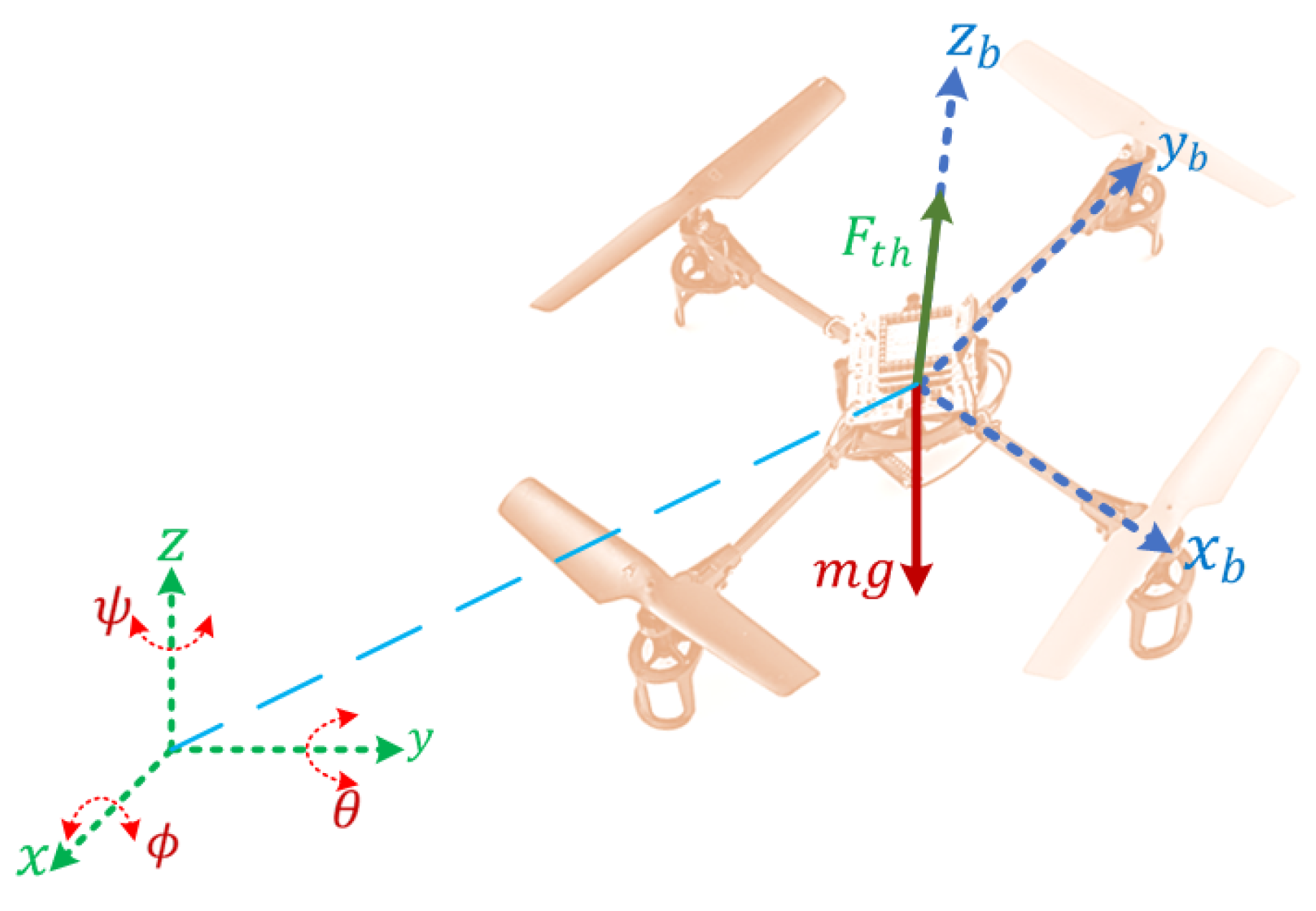
Figure 5.
The quadrotor waypoint navigation FOPID control structure.
Figure 5.
The quadrotor waypoint navigation FOPID control structure.
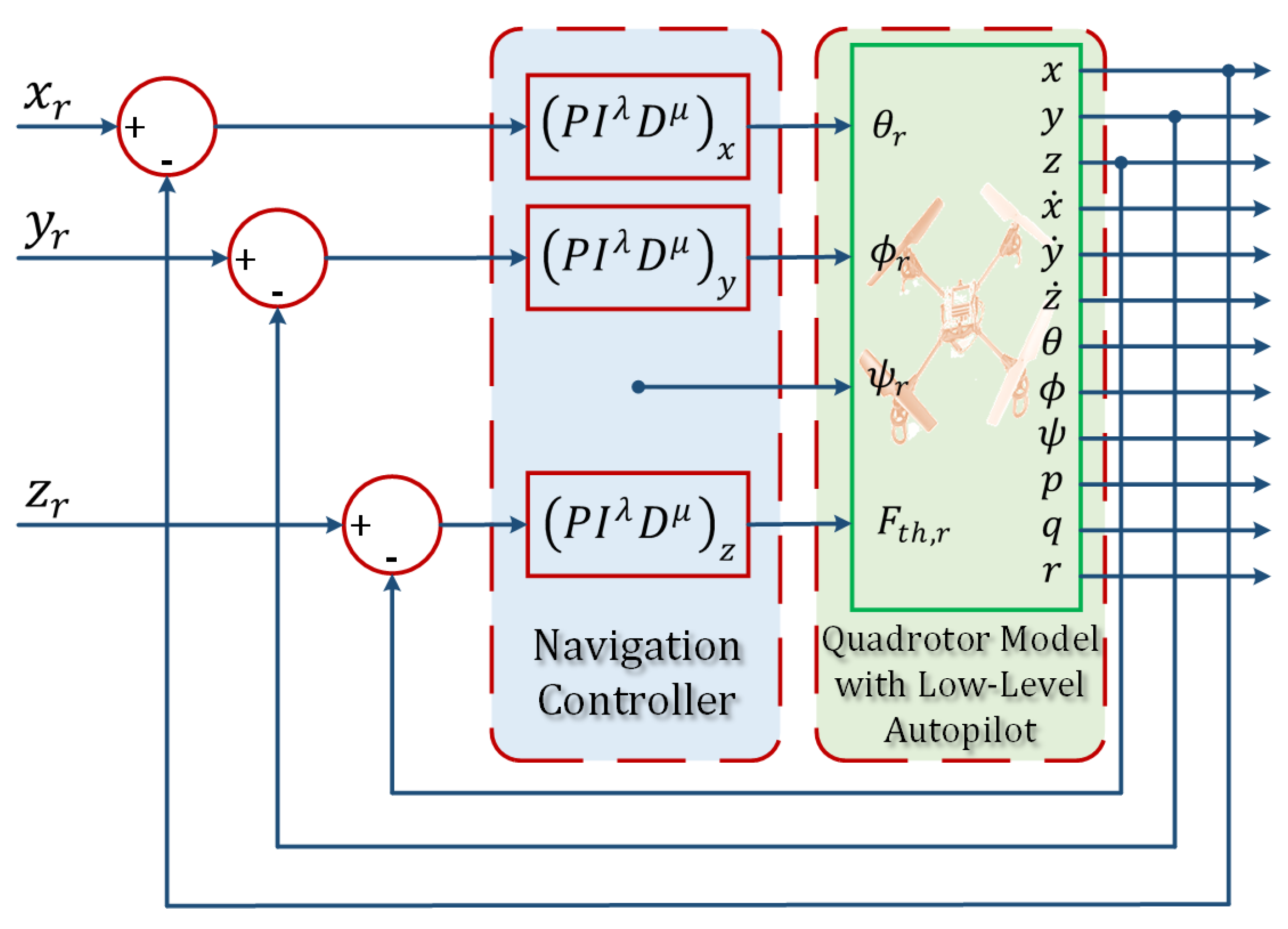
Figure 6.
The twin-rotor copter physical setup.
Figure 6.
The twin-rotor copter physical setup.
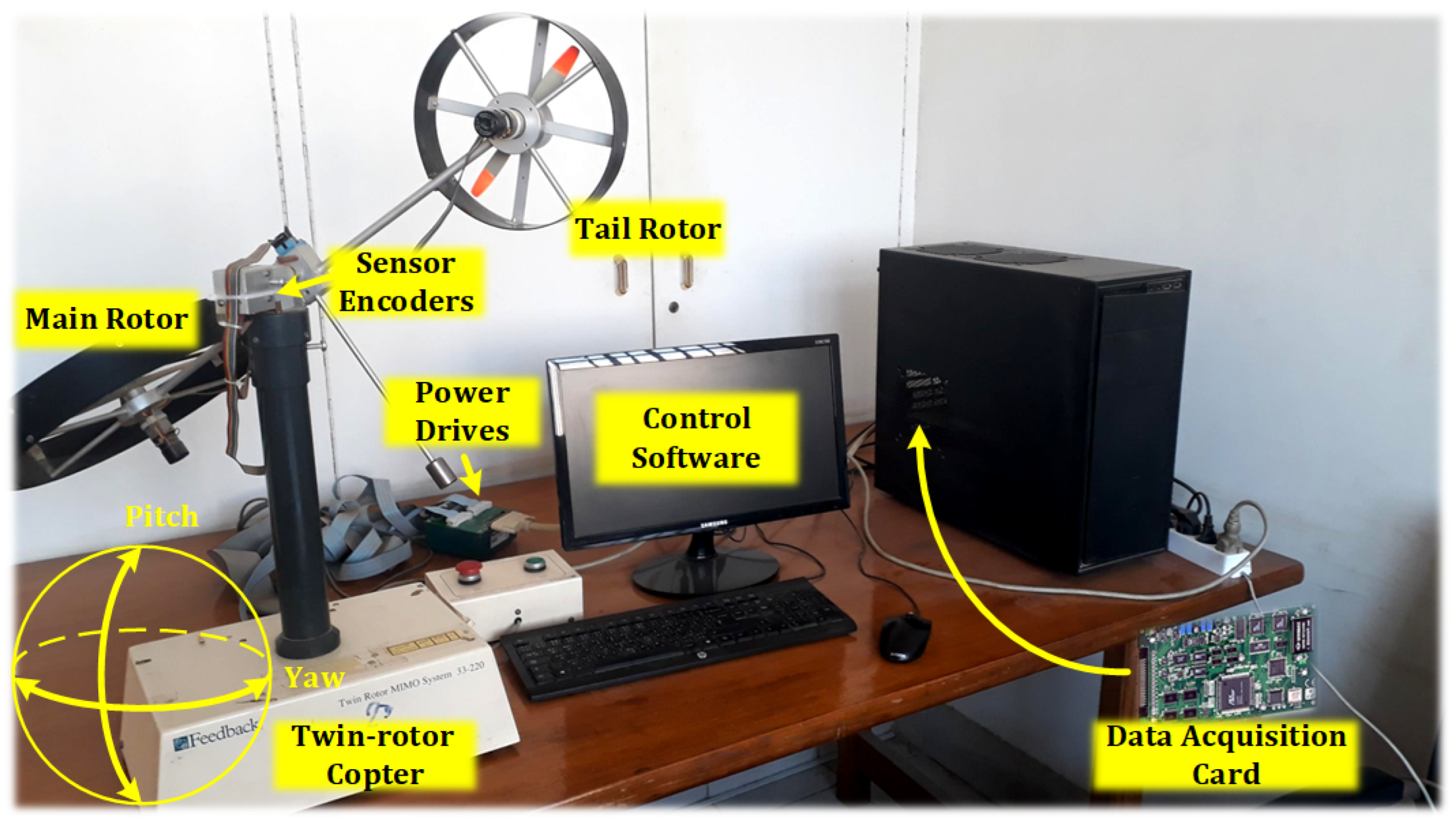
Figure 7.
The twin-rotor copter cross-coupled FOPID control.
Figure 7.
The twin-rotor copter cross-coupled FOPID control.
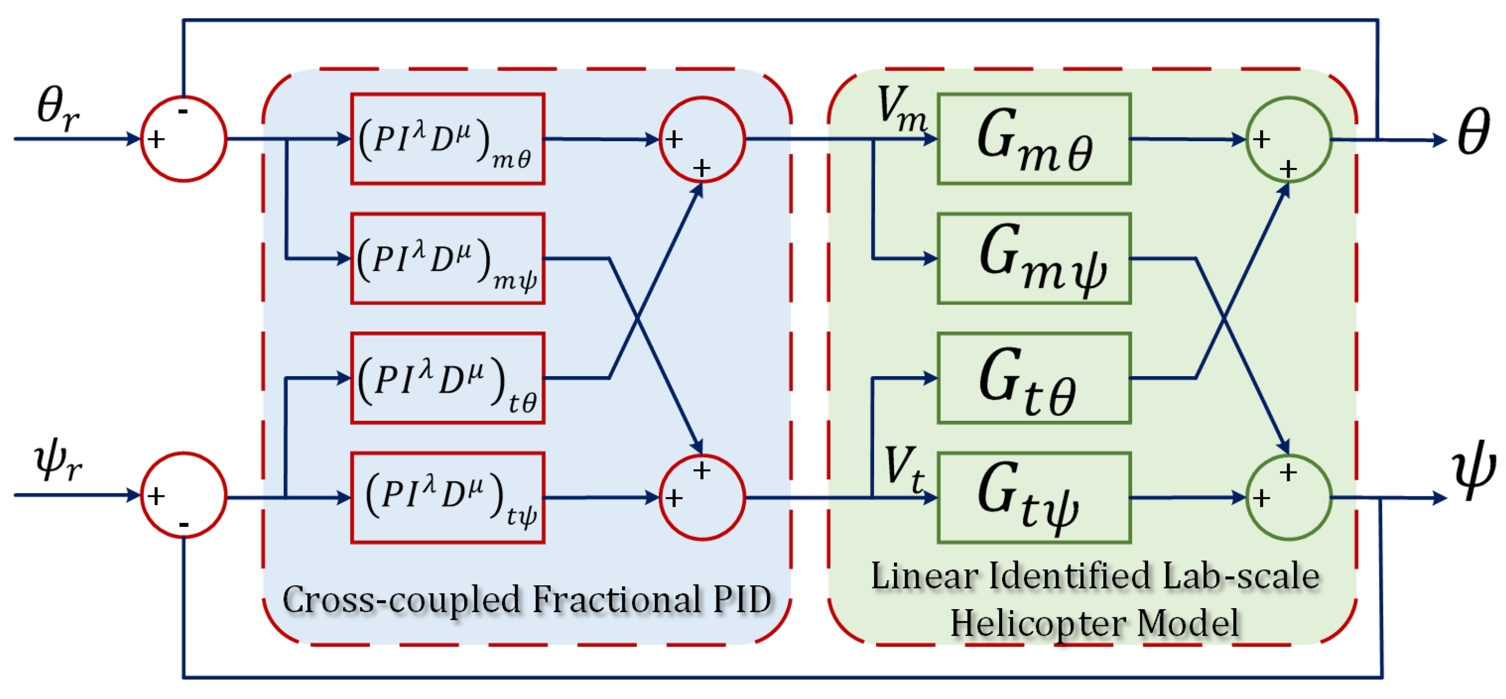
Figure 8.
Stability boundaries in the – plane for arbitrarily selected values of .
Figure 8.
Stability boundaries in the – plane for arbitrarily selected values of .
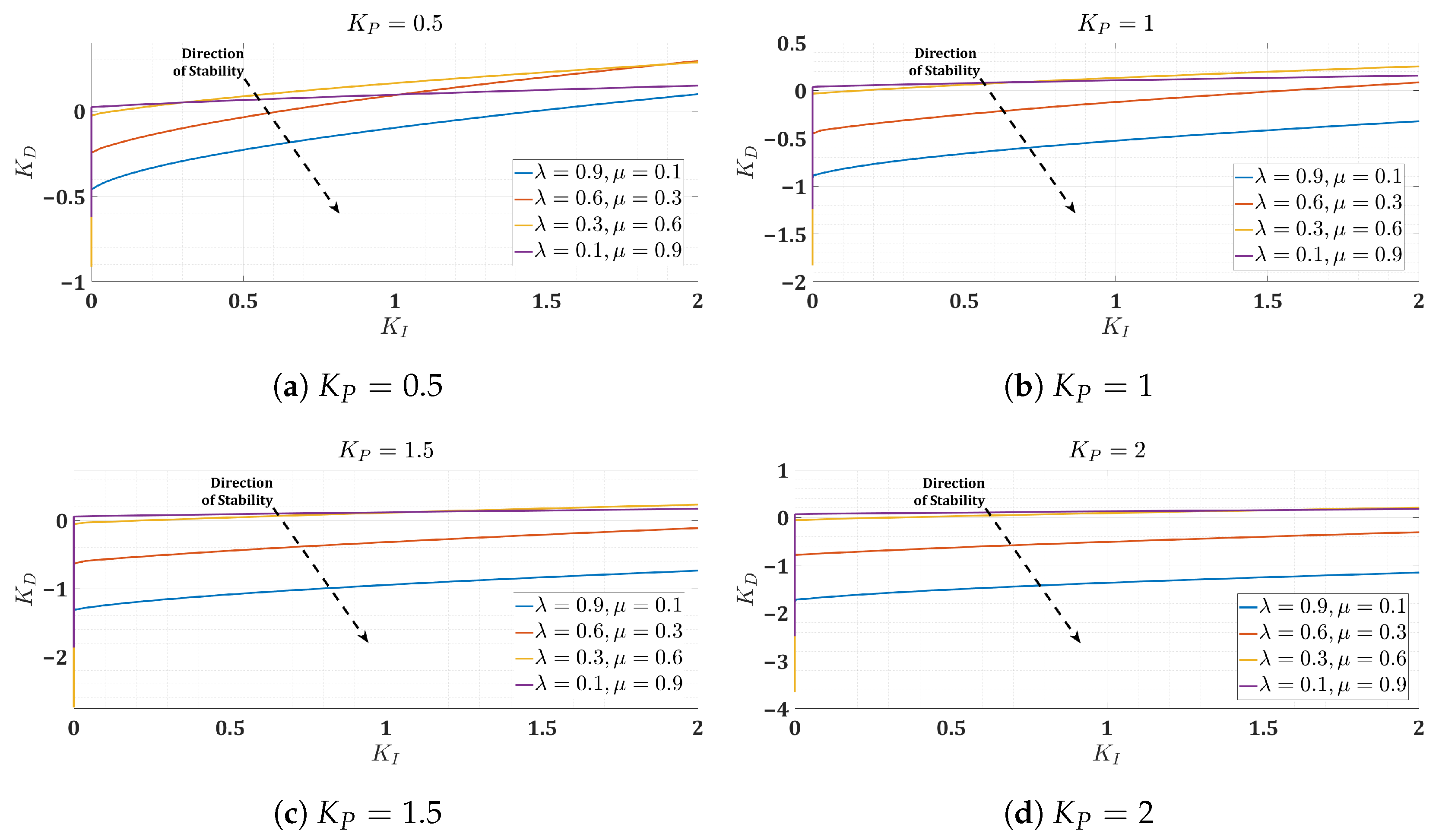
Figure 9.
Flowchart of the surrogate optimization algorithm.
Figure 9.
Flowchart of the surrogate optimization algorithm.
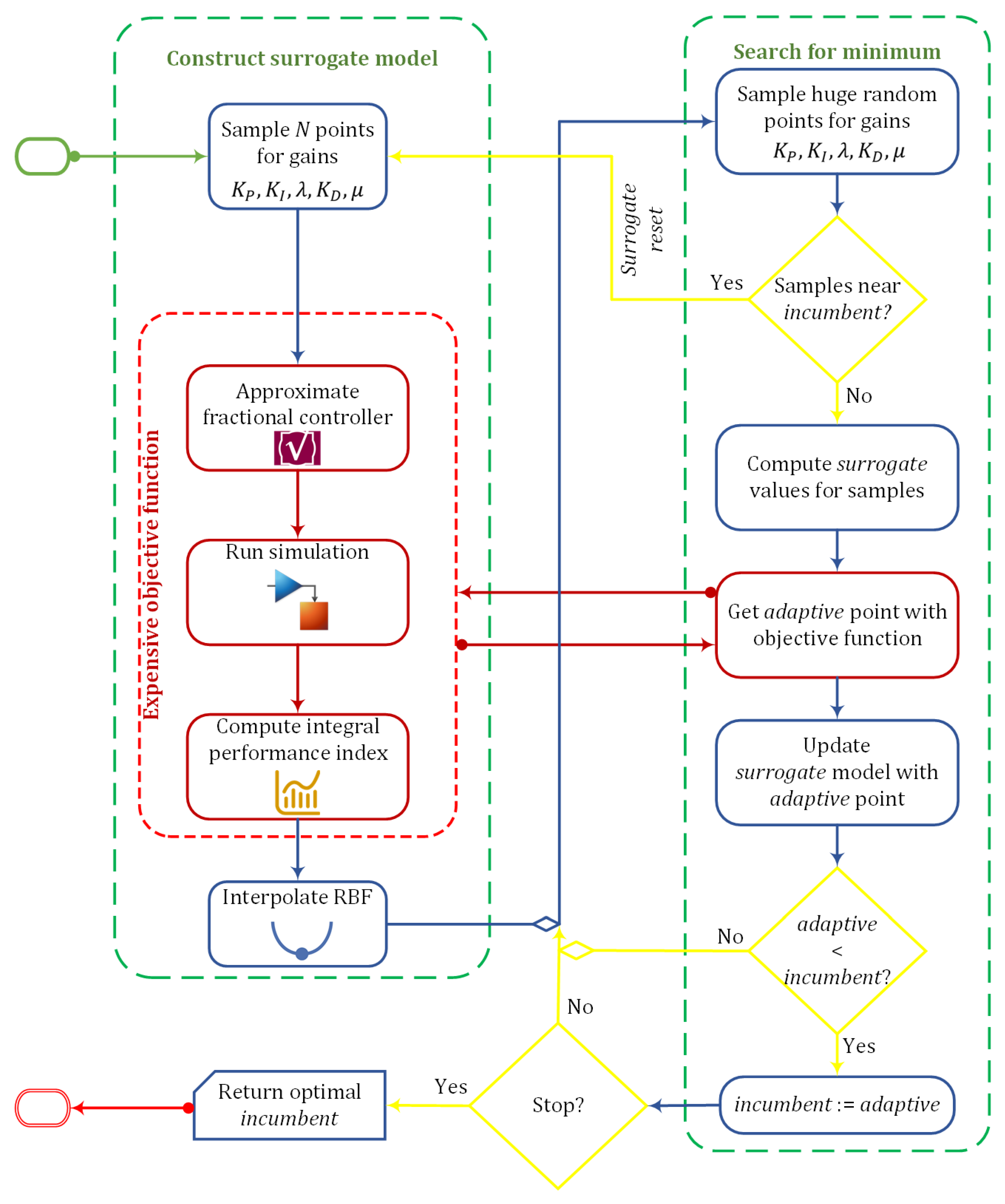
Figure 10.
Conceptual plot of the surrogate optimization algorithm.
Figure 10.
Conceptual plot of the surrogate optimization algorithm.
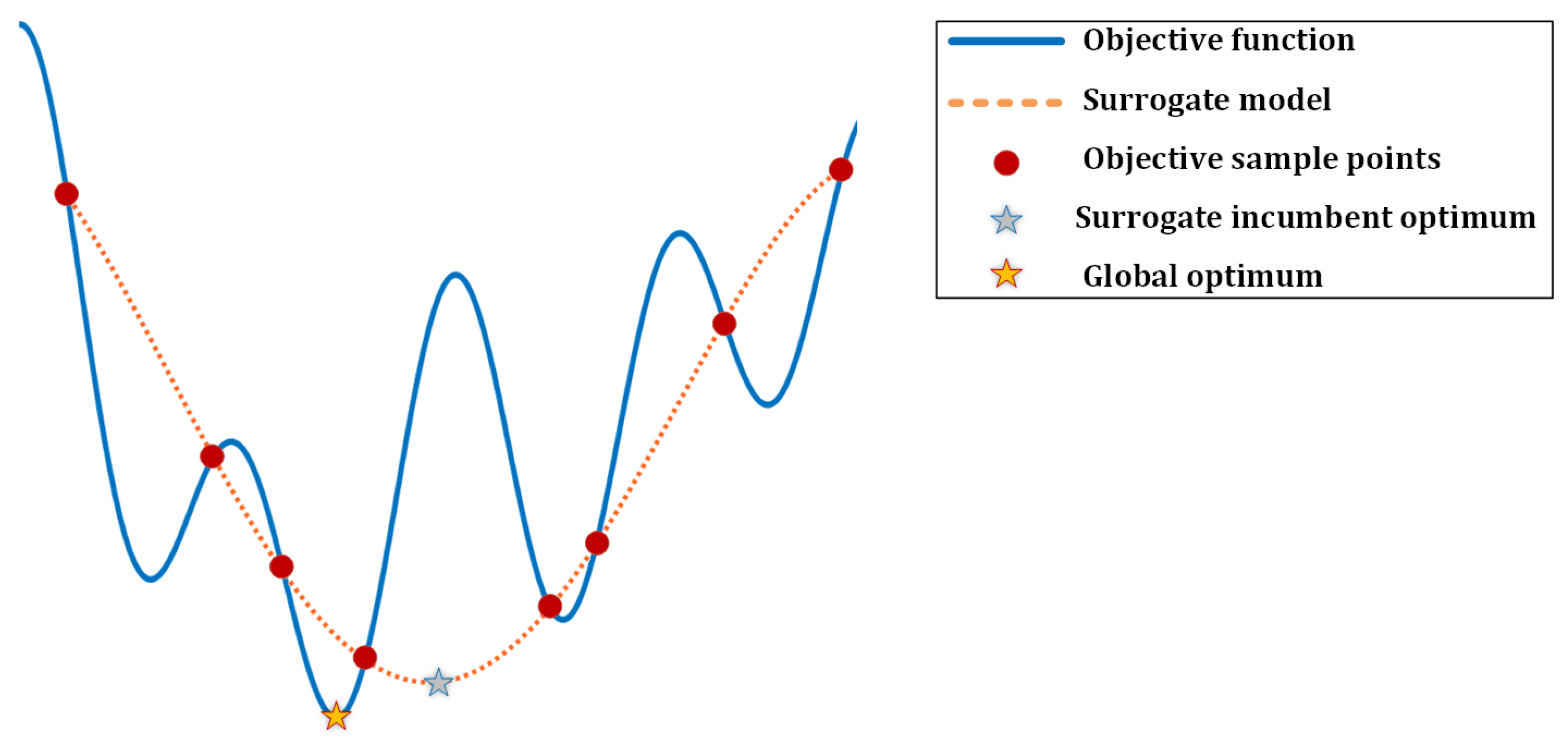
Figure 11.
Position step responses for the quadrotor.
Figure 11.
Position step responses for the quadrotor.
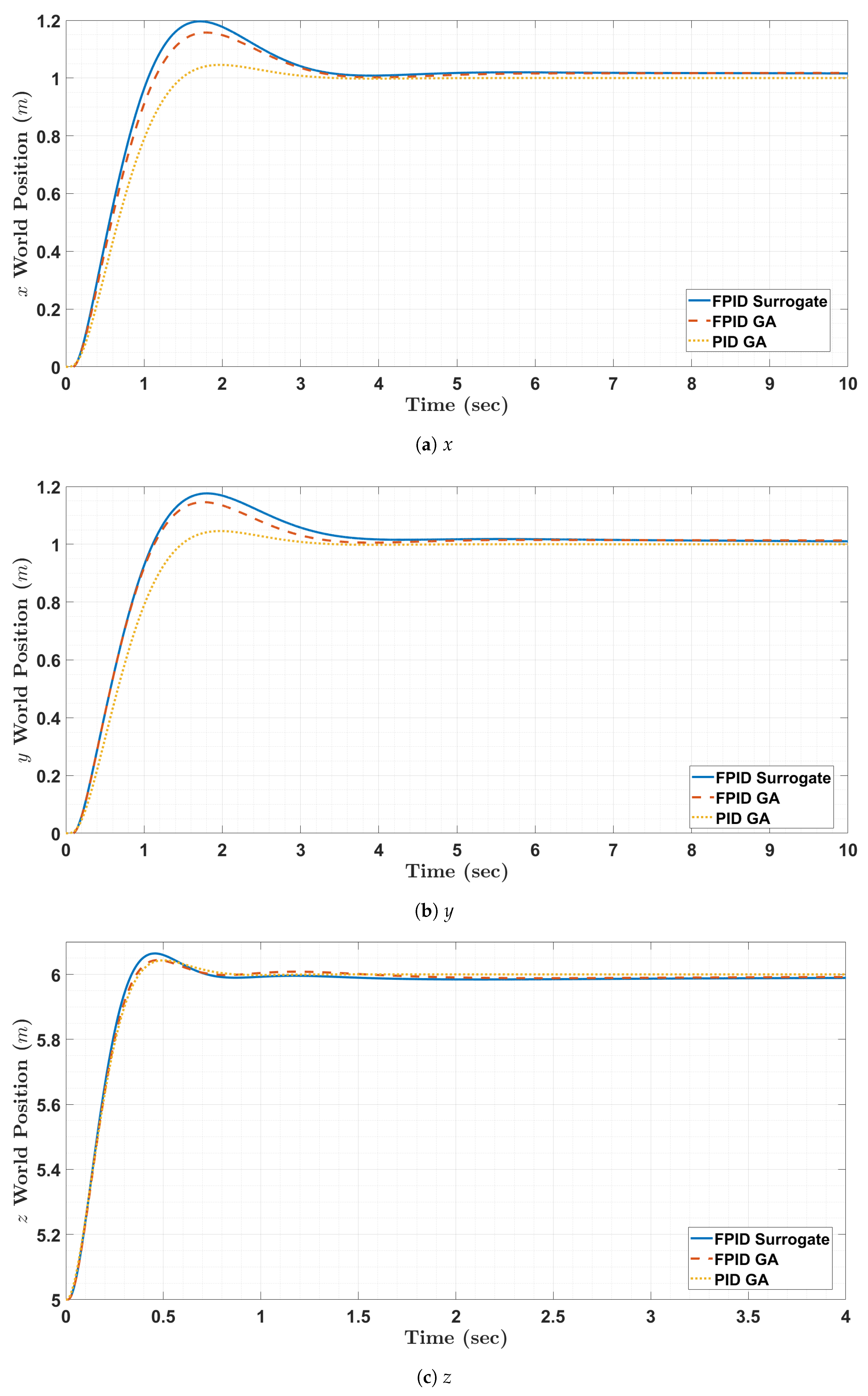
Figure 12.
Simulation of the mission scenario for the quadrotor.
Figure 12.
Simulation of the mission scenario for the quadrotor.
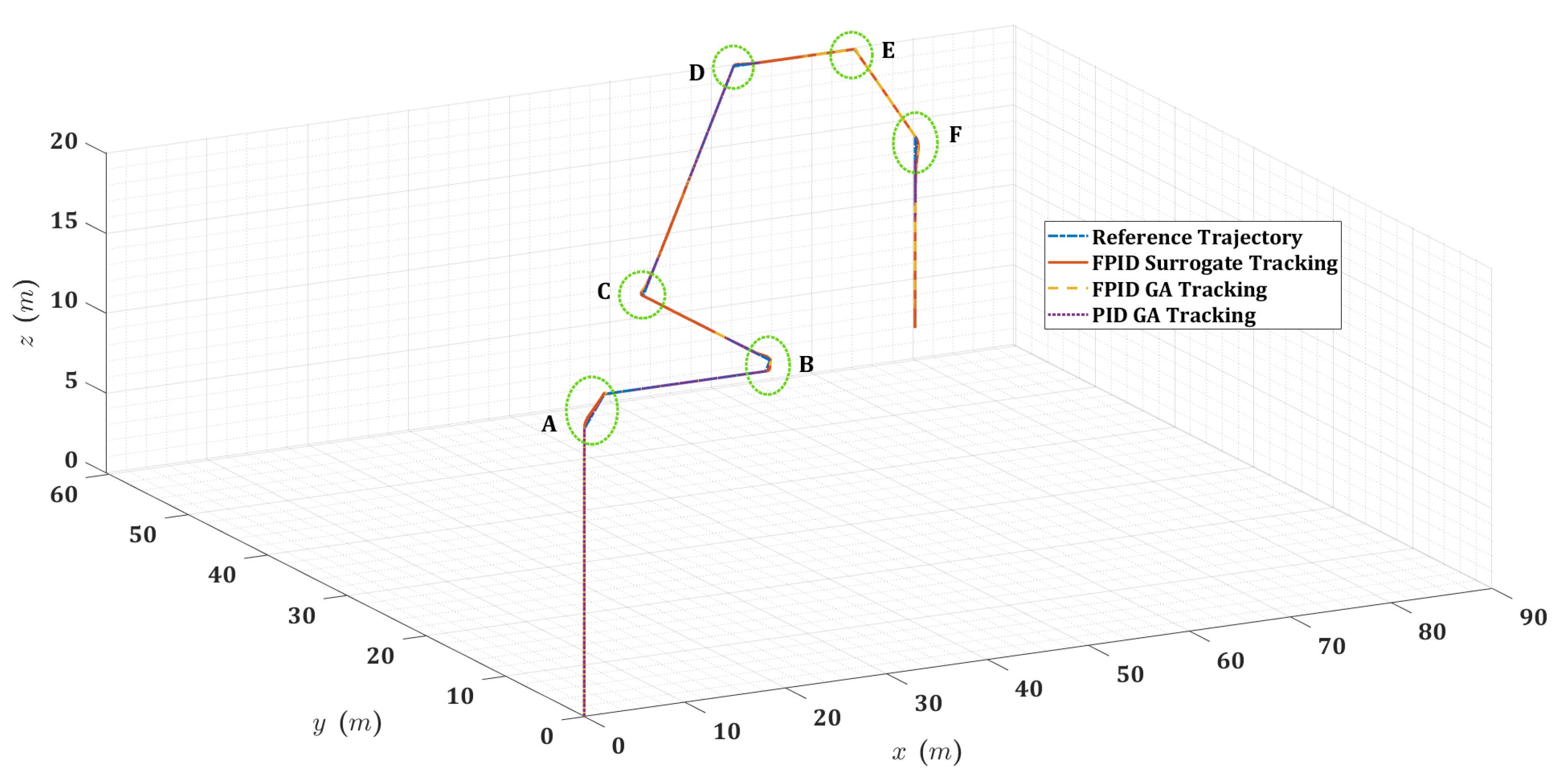
Figure 13.
Zoomed 2D planar view for the quadrotor mission trajectory at transitional regions (A, B, and C).
Figure 13.
Zoomed 2D planar view for the quadrotor mission trajectory at transitional regions (A, B, and C).
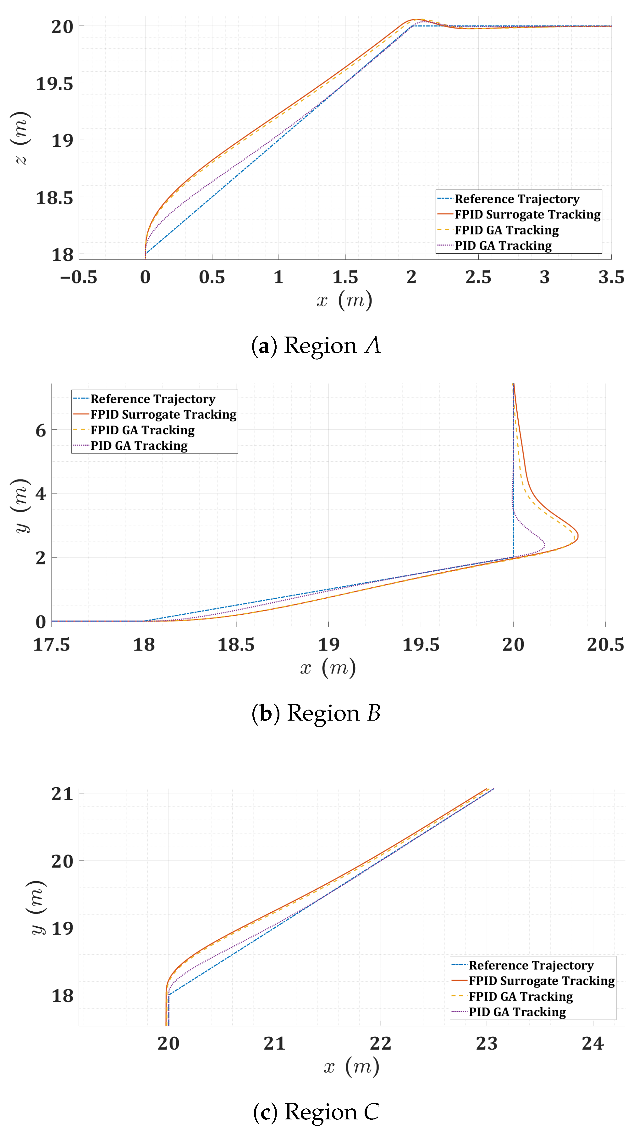
Figure 14.
Zoomed 2D planar view for the quadrotor mission trajectory at transitional regions (D, E, and F).
Figure 14.
Zoomed 2D planar view for the quadrotor mission trajectory at transitional regions (D, E, and F).
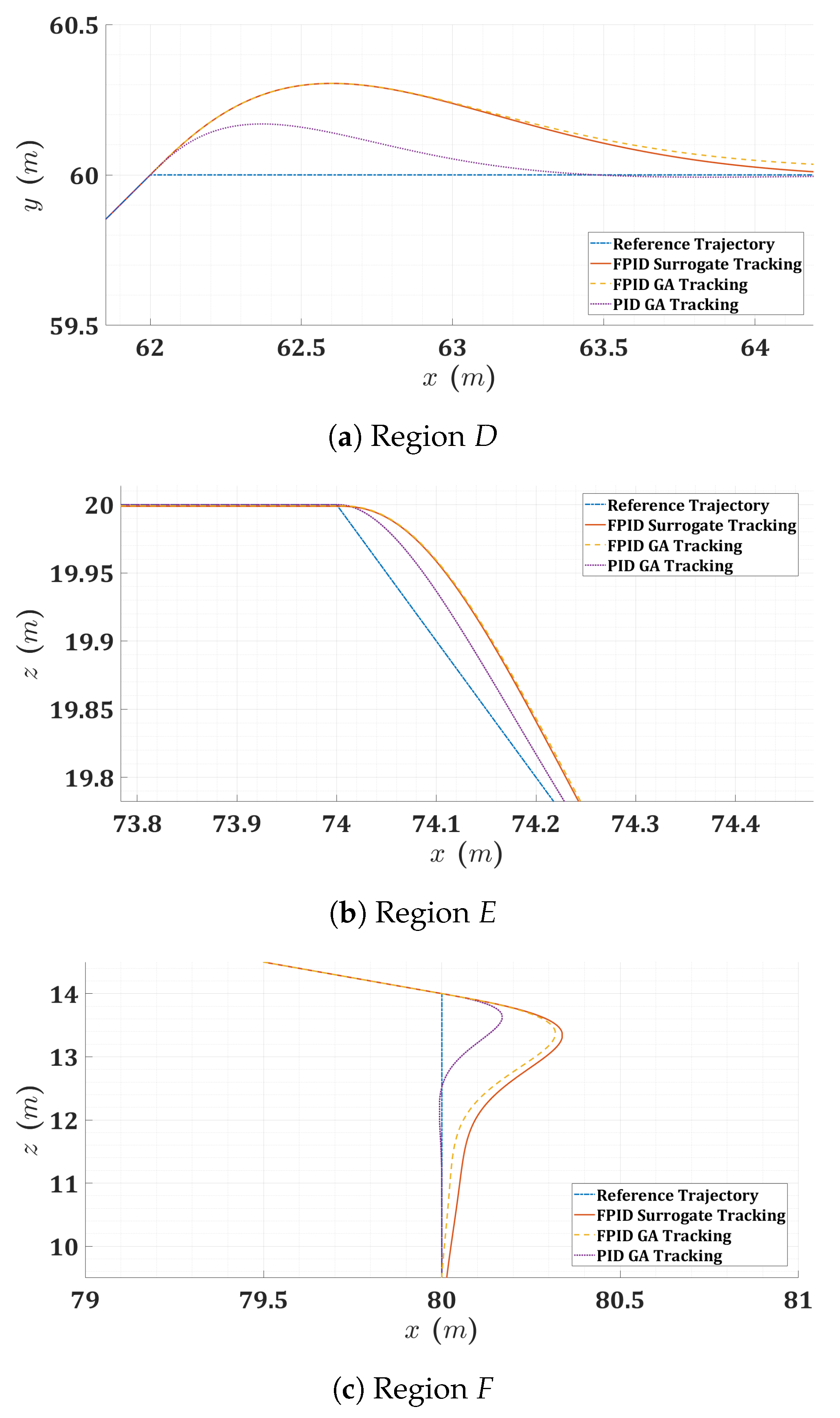
Figure 15.
Histogram of control actions for the quadrotor.
Figure 15.
Histogram of control actions for the quadrotor.
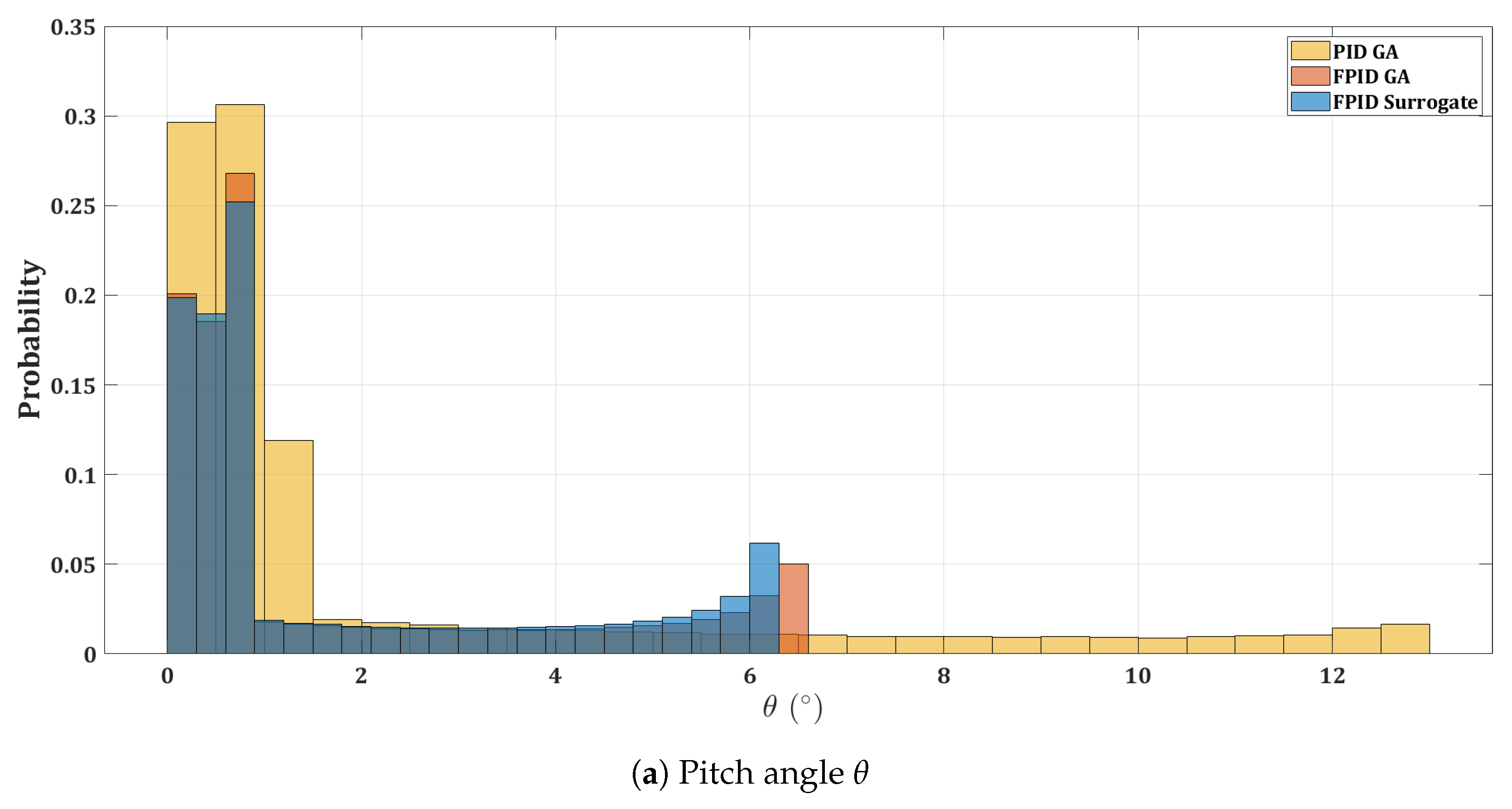
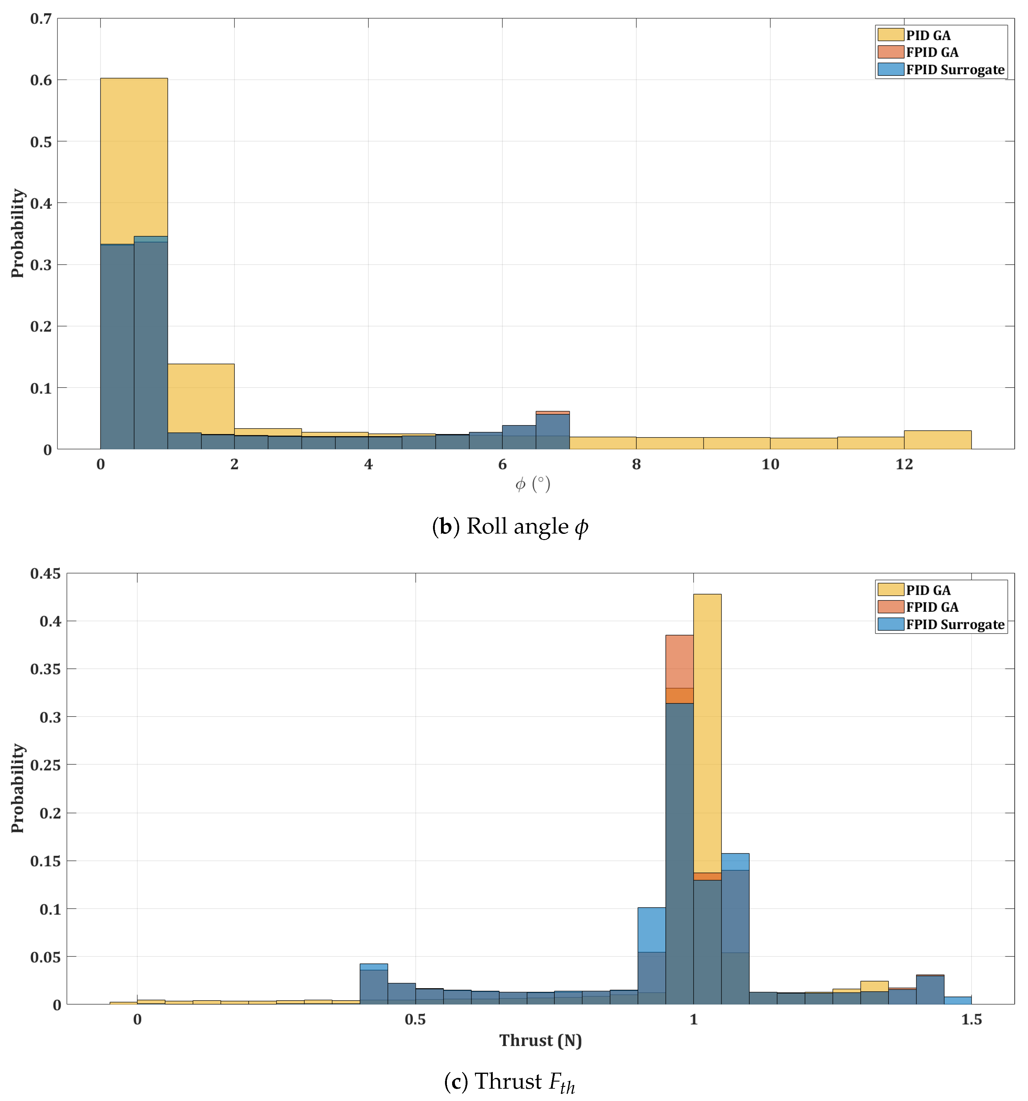
Figure 16.
Acceleration power spectral density for the quadrotor mission.
Figure 16.
Acceleration power spectral density for the quadrotor mission.
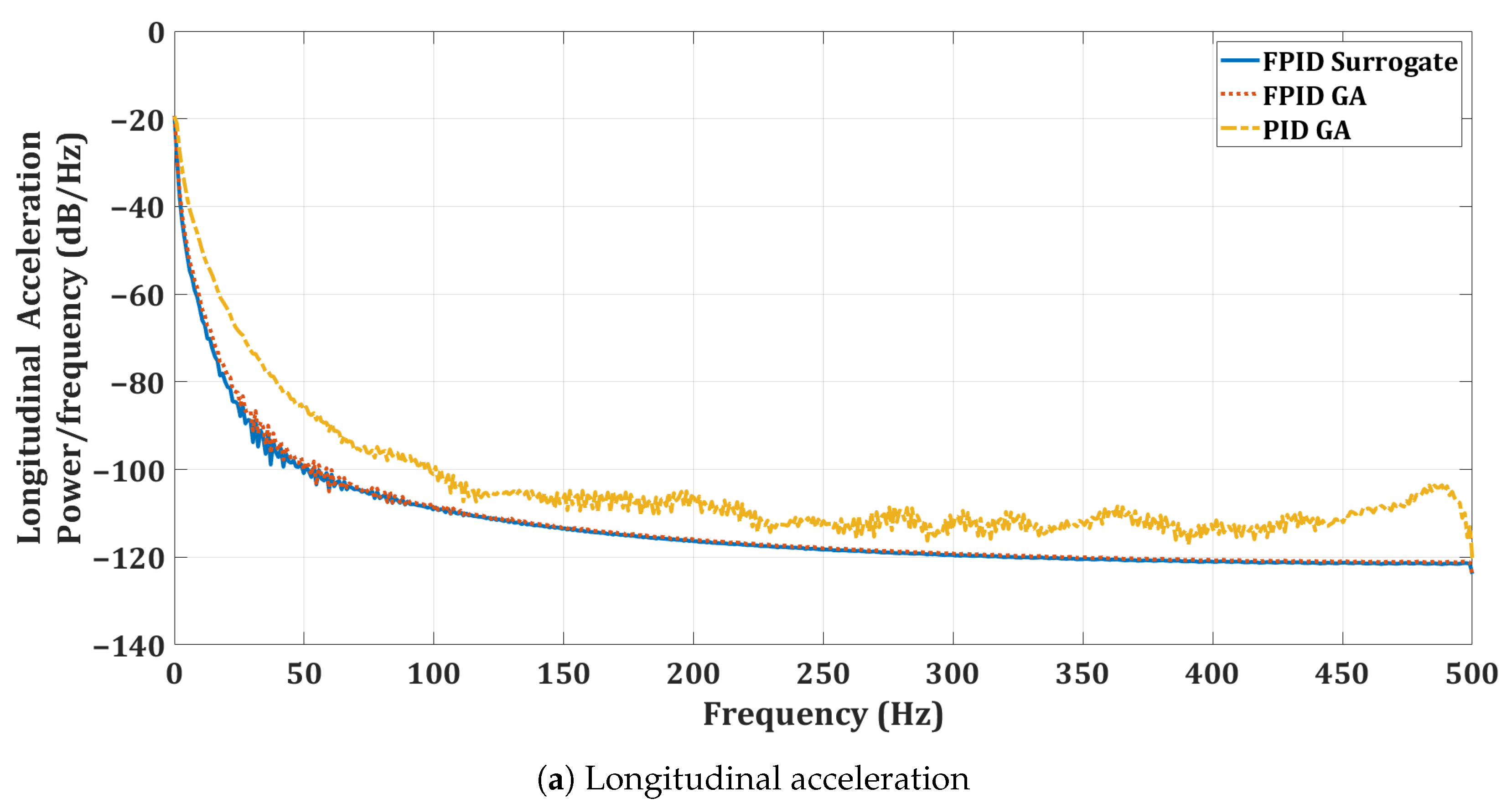
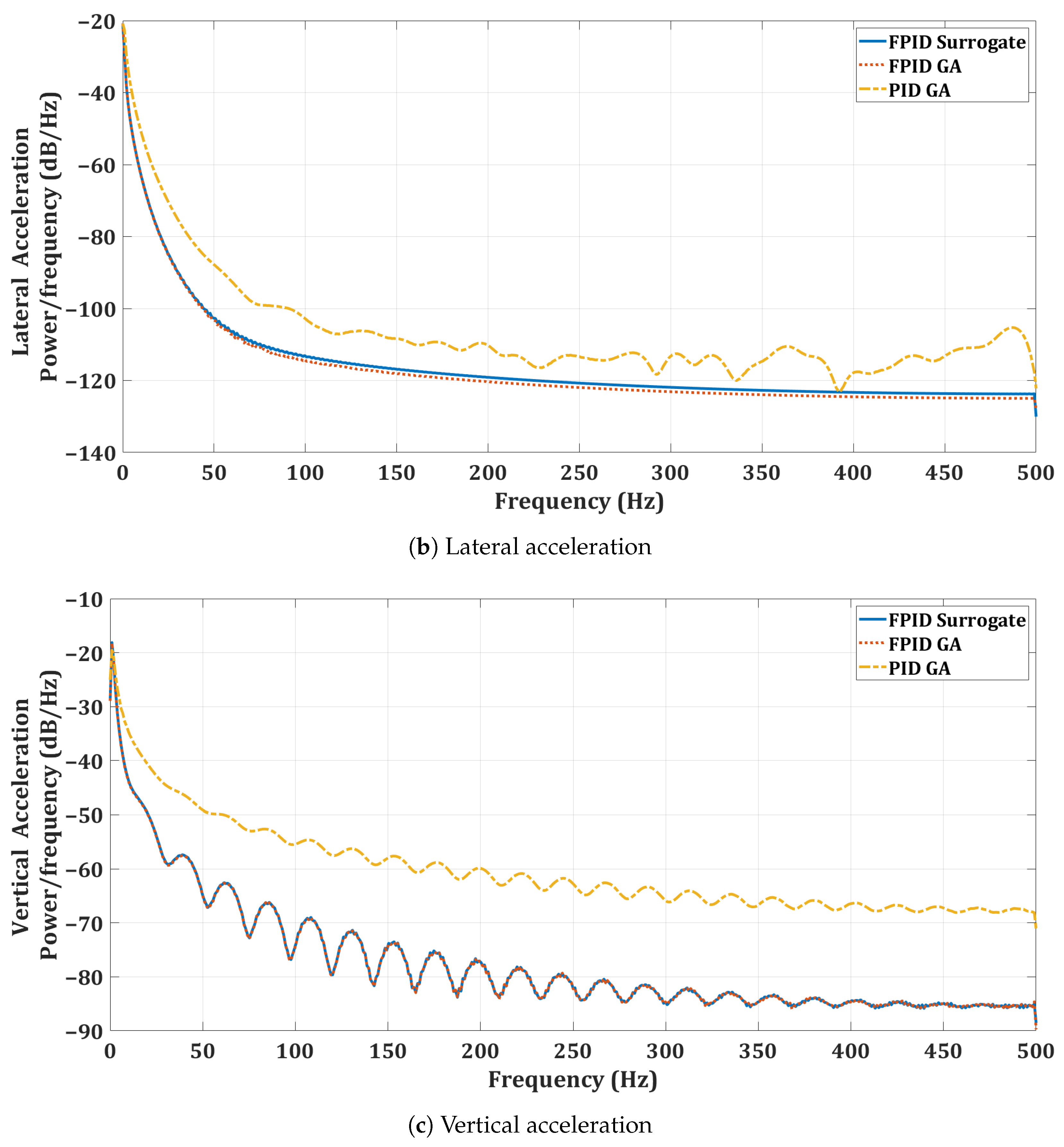
Figure 17.
Visualization of the optimal FOPID controllers for the twin-rotor copter.
Figure 17.
Visualization of the optimal FOPID controllers for the twin-rotor copter.
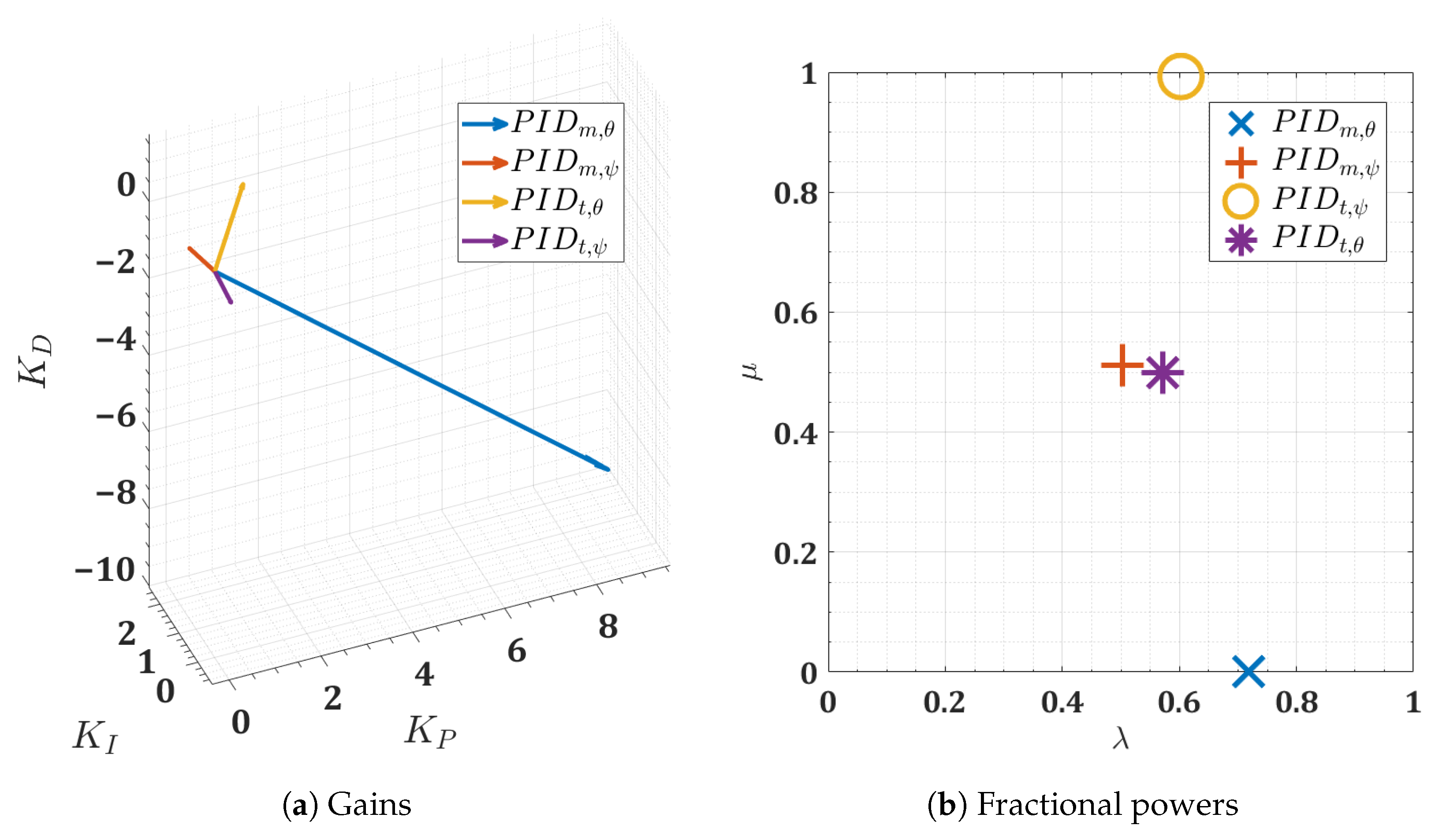
Figure 18.
Convergence of surrogate optimization for the FOPID controllers of the twin-rotor copter.
Figure 18.
Convergence of surrogate optimization for the FOPID controllers of the twin-rotor copter.
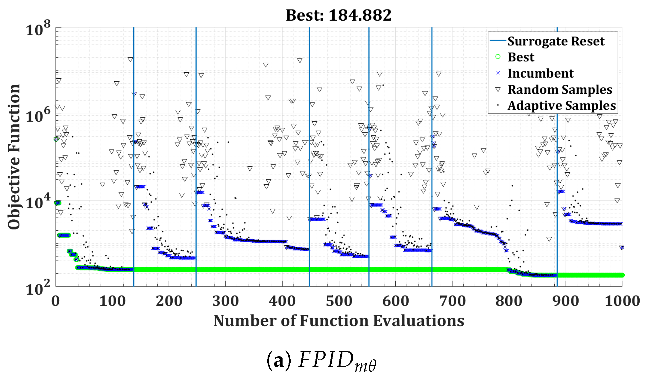
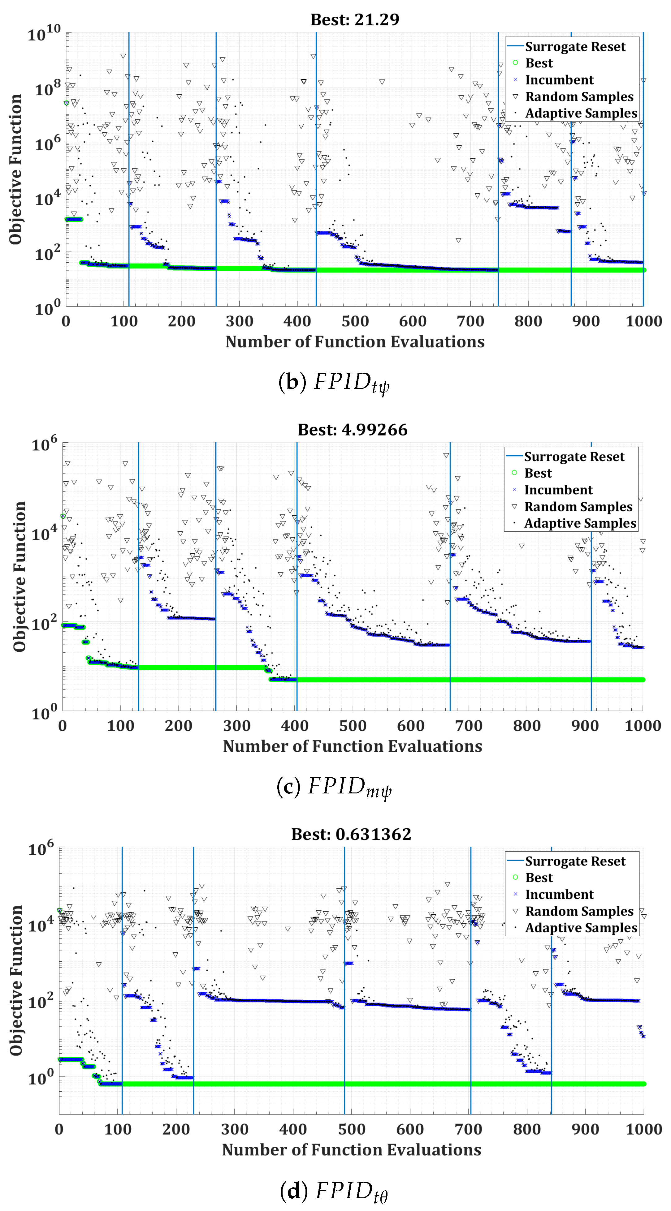
Figure 19.
Real-time orientation step responses for the twin-rotor copter.
Figure 19.
Real-time orientation step responses for the twin-rotor copter.
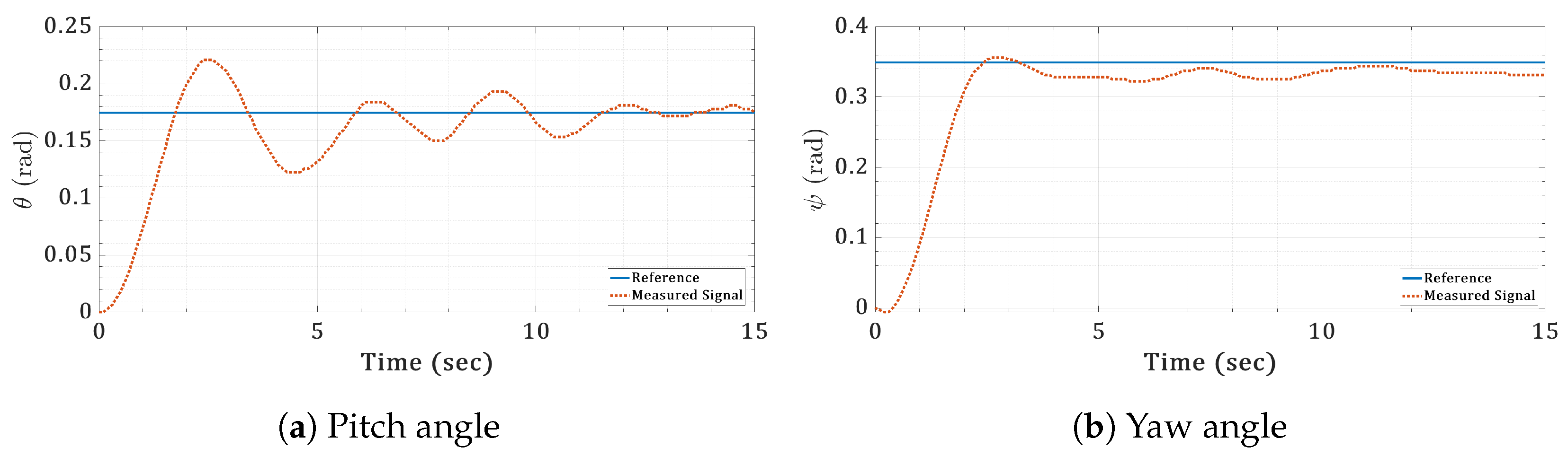
Figure 20.
Real-timecontrol actions of the step commands for the twin-rotor copter.
Figure 20.
Real-timecontrol actions of the step commands for the twin-rotor copter.
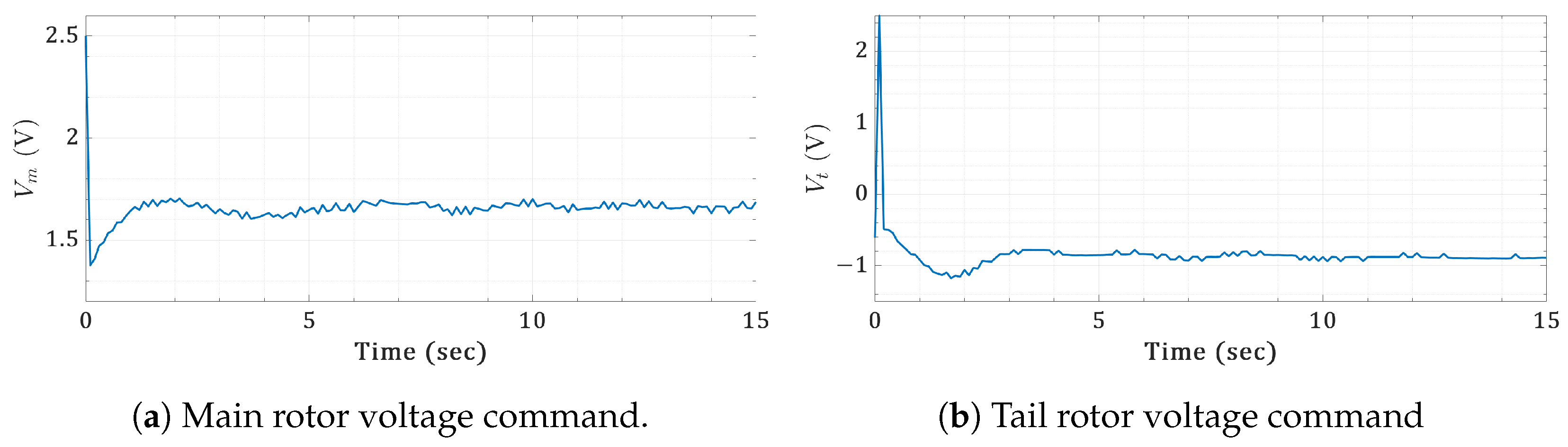
Figure 21.
Real-time orientation sinusoidal responses for the twin-rotor copter.
Figure 21.
Real-time orientation sinusoidal responses for the twin-rotor copter.
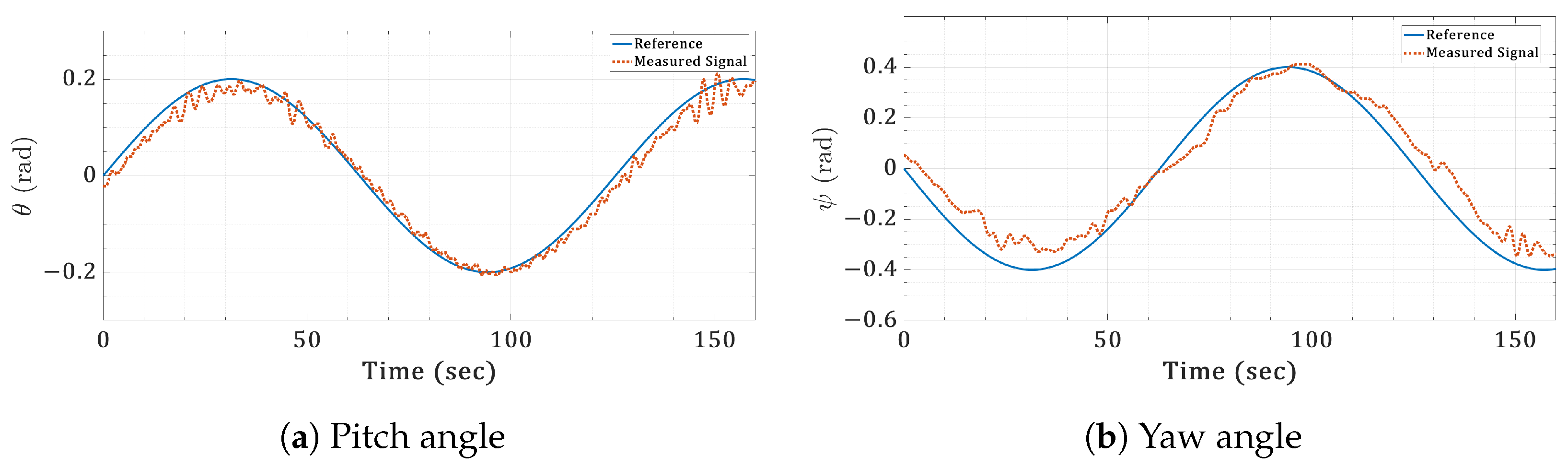
Figure 22.
Real-time control actions of the sinusoidal commands for the twin-rotor copter.
Figure 22.
Real-time control actions of the sinusoidal commands for the twin-rotor copter.
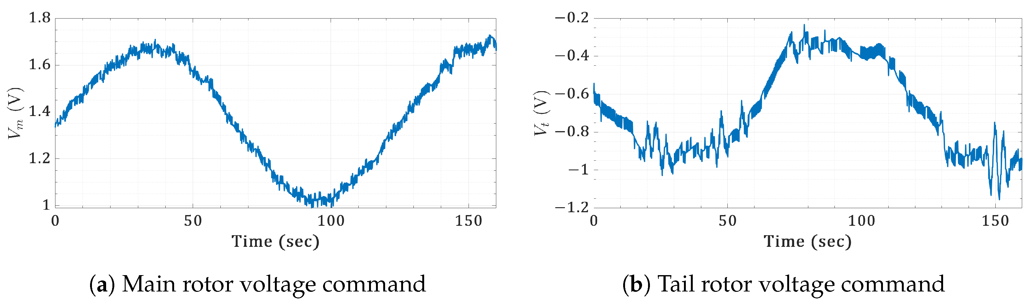
Figure 23.
Real-time orientation sawtooth responses for the twin-rotor copter.
Figure 23.
Real-time orientation sawtooth responses for the twin-rotor copter.
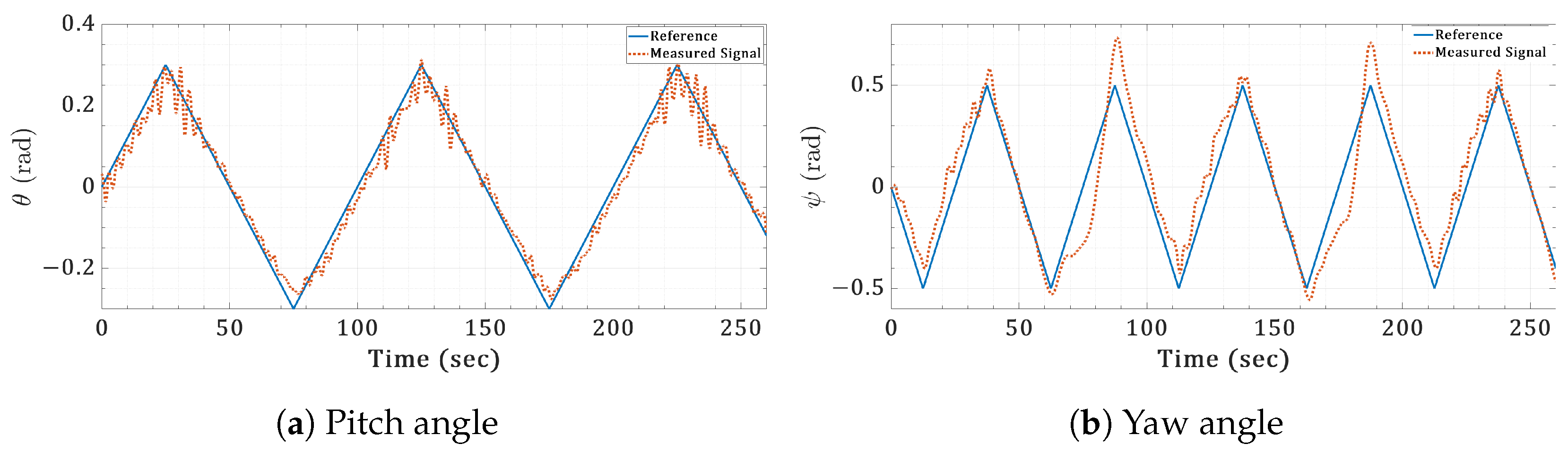
Figure 24.
Real-time control actions of the sawtooth commands for the twin-rotor copter.
Figure 24.
Real-time control actions of the sawtooth commands for the twin-rotor copter.
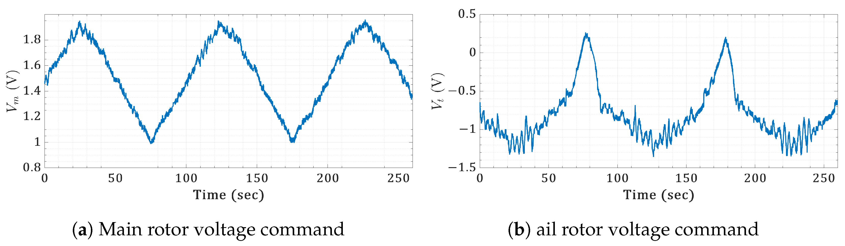
Table 1.
The quadrotor model parameters [67].
The quadrotor model parameters [67].
Table 1.
The quadrotor model parameters [67].
The quadrotor model parameters [67].
| Parameter | Value |
|---|---|
| (s−2) | 3402.97 |
| (s−1) | 116.67 |
| (s−2) | 3402.97 |
| (s−1) | 116.67 |
| (s−1) | 1950 |
| (s−1) | 3900 |
| m (kg) | 0.1 |
Table 2.
Statistical measures of the quadrotor controller optimization.
Table 2.
Statistical measures of the quadrotor controller optimization.
| Axis | Controller | Objective Function | Computation Time (min) | ||||||
|---|---|---|---|---|---|---|---|---|---|
| Min. Value | Mean | Median | Standard Deviation |
Average Simulations Count |
Mean | Median | Standard Deviation |
||
| x | PID-GA | 664.2483 | 665.0124 | 664.3411 | 1.1576 | 2450 | 14.0791 | 14.0254 | 1.4368 |
| FOPID-GA | 672.5661 | 679.6325 | 678.4195 | 6.8963 | 2517 | 26.3810 | 26.3464 | 3.1829 | |
| FOPID-Surrogate | 672.0003 | 683.4908 | 680.4865 | 8.3657 | 1000 | 11.1183 | 10.9377 | 0.5672 | |
| y | PID-GA | 664.2483 | 665.0124 | 664.3411 | 1.1576 | 2450 | 7.0880 | 7.0214 | 0.9581 |
| FOPID-GA | 673.3710 | 680.4129 | 676.7823 | 8.0841 | 2497 | 21.9964 | 20.4116 | 4.2519 | |
| FOPID-Surrogate | 677.0695 | 682.9058 | 681.5786 | 5.5742 | 1000 | 10.4262 | 10.0240 | 0.7907 | |
| z | PID-GA | 274.7040 | 274.7089 | 274.7041 | 0.0125 | 2450 | 9.5922 | 9.3179 | 1.4732 |
| FOPID-GA | 286.9981 | 289.5838 | 288.8558 | 3.1095 | 2450 | 25.4097 | 23.9121 | 5.1696 | |
| FOPID-Surrogate | 287.9273 | 289.4379 | 289.1571 | 1.2448 | 1000 | 19.3086 | 19.3221 | 1.0178 | |
Table 3.
PID and FOPID gains for the quadrotor controllers.
Table 3.
PID and FOPID gains for the quadrotor controllers.
| Axis | Controller | |||||
|---|---|---|---|---|---|---|
| x | PID-GA | 0.4598 | 0 | 1 | 0.3061 | 1 |
| FOPID-GA | 0.0696 | 0.0089 | 0.9053 | 0.2196 | 0.7202 | |
| FOPID-Surrogate | 0 | 0.0205 | 0.6440 | 0.2480 | 0.6292 | |
| y | PID-GA | 0.4598 | 0 | 1 | 0.3061 | 1 |
| FOPID-GA | 0.0574 | 0.0244 | 0.5658 | 0.2389 | 0.7197 | |
| FOPID-Surrogate | 0.0376 | 0.0544 | 0.4275 | 0.2375 | 0.7272 | |
| z | PID-GA | 8.6983 | 5.8476 | 1 | 1.3159 | 1 |
| FOPID-GA | 0.7844 | 7.6204 | 0.8063 | 2.1821 | 0.6411 | |
| FOPID-Surrogate | 0.6607 | 7.9986 | 0.7507 | 2.2529 | 0.6387 |
Table 4.
Time-domain characteristics for quadrotor step responses.
Table 4.
Time-domain characteristics for quadrotor step responses.
| Axis | Controller | Rise Time (s) | Overshoot | Settling Time (s) | Settling Error |
|---|---|---|---|---|---|
| x | PID-GA | 0.9164 | 4.5587 | 2.6726 | 1.5332 |
| FOPID-GA | 0.7591 | 13.7547 | 2.9700 | 0.0177 | |
| FOPID-Surrogate | 0.6958 | 17.7479 | 3.0561 | 0.0161 | |
| y | PID-GA | 0.9164 | 4.5587 | 2.6726 | 1.5332 |
| FOPID-GA | 0.7444 | 13.0912 | 2.9666 | 0.0131 | |
| FOPID-Surrogate | 0.7329 | 16.4277 | 3.4230 | 0.0101 | |
| z | PID-GA | 0.2402 | 4.3196 | 0.6700 | 3.1186 |
| FOPID-GA | 0.2283 | 4.3987 | 0.6157 | 0.0042 | |
| FOPID-Surrogate | 0.2163 | 6.4502 | 0.6352 | 0.0059 |
Table 5.
Statistical measures of the twin-rotor copter controller optimization.
Table 5.
Statistical measures of the twin-rotor copter controller optimization.
| Controller | Objective Function | Computation Time (min) | |||
|---|---|---|---|---|---|
| Minimum Value | Mean | Standard Deviation | Mean | Standard Deviation | |
| 184.8821 | 207.2058 | 26.6892 | 9.8651 | 0.2540 | |
| 4.9927 | 5.4286 | 0.3315 | 14.2360 | 0.6657 | |
| 0.6314 | 0.7114 | 0.0508 | 15.1317 | 0.3795 | |
| 21.2900 | 23.3846 | 1.5300 | 10.2655 | 1.1018 | |
Table 6.
FOPID gains for the twin-rotor copter controller.
Table 6.
FOPID gains for the twin-rotor copter controller.
| Controller | |||||
|---|---|---|---|---|---|
[ad_2]