Numerical Simulation Study on Braking Performance of a New Eddy Current-Hydrodynamic Hybrid Retarder
1. Introduction
The retarder is a kind of auxiliary braking device for automobiles which can effectively improve the safety of heavy vehicles and reduce the emission of non-exhaust particles [1,2]. The commonly used vehicle retarders are mainly divided into ECRs and HRs. The existing ECR has fast response speed and large braking torque at low speeds but low braking power density at high speeds and severe thermal degradation during continuous braking [3]. However, the existing HR is light in weight, small in volume, and large in braking torque at high speeds but slow response and low power density at low speeds [4]. To sum up, the ECRs and HRs are complementary in braking characteristics.
To improve the braking performance of the ECRs, Tian et al. [5] proposed an internal liquid-cooled ECR, which solves the problems of torque heat decay and coil ablation during continuous braking. Zhang et al. [6,7] proposed a self-excited ECR to solve the power consumption problem during operation. Although the above research improved the braking performance of ECRs to some extent, it still does not solve the problem of low braking power at high speeds.
In terms of HRs, Yan et al. [8] used numerical simulation methods to study the velocity distribution, pressure distribution, and turbulent kinetic energy distribution of liquid flow inside the HR. Wei et al. [9,10] conducted research on the suppression method of air loss, heat flow field, and parameters affecting the effectiveness characteristics of the HRs. Li et al. [11] conducted in-depth research on the cavitation characteristics of the transient coupled flow field of the HR. In summary, the research on HRs mainly focuses on pure hydraulic braking, such as air loss, thermal field, flow field, and pressure field. Due to the characteristics of hydraulic braking itself, these studies cannot truly improve the low-speed braking performance of HRs. However, Gao et al. [12] and Zhang et al. [13], respectively, proposed a hydraulic electric composite retarder and verified its braking performance advantages via recent experiments.
To further improve the power density of the retarder at full speed and ensure the safety of vehicle deceleration, a new eddy current-hydrodynamic hybrid retarder (ECHHR) is proposed. The electromagnetic field distribution, flow field velocity, and flow field pressure distribution inside the ECHHR are analyzed by the finite element analysis method, and the braking characteristics of the ECHHR under different working conditions are obtained by experiments.
2. Structure and Working Principles
As shown in Figure 1, the proposed ECHHR is mainly composed of a rotor, a stator, and an independently wound excitation coil. The rotor is a double disk integral structure, and the left and right outer sides of the rotor are arranged with hydraulic circulation semicircles of the hydraulic retarder. The stator comprises a left stator, a right stator, and a stator connector with a salient pole structure. The left and right stators are symmetrical in structure, and one side of the left and right stators is arranged with a hydraulic circulation semicircle of a hydraulic retarder. The excitation coils are fixed on the stator connection, and the wire is connected to the electronic control unit via the outlet on the stator. The ECHHR adds the function of eddy current braking to the structure of traditional hydraulic retarders, and both eddy current braking and hydraulic braking share the rotor of the ECHHR.
The blades of the stator and rotor form a working chamber of hydraulic braking. Since the left and right structures of the ECHHR are symmetrical, two hydraulic retarders are formed. When the hydraulic braking of the ECHHR starts to work, the oil enters the hydraulic working chamber through the upper oil circuit. As the rotor rotates, the rotating rotor blade drives the oil in the hydraulic working chamber to undergo centrifugal acceleration movement. At the same time, the high-speed moving oil impacts the stator blades, and the rotor blades are also impacted by the oil, thereby hindering the rotation of the rotor. In this process, the oil constantly flows into the hydraulic working chamber from the liquid inlet, through the lower oil circuit, and finally discharges to the radiator from the liquid outlet so as to dissipate the heat energy converted by the rotating mechanical energy of the rotor. The rotor and stator connections are made of highly conductive magnet materials. When the excitation coils are excited with direct current (DC), a magnetic field generated by the excitation coils is closed via the left side of the rotor, the left air gap, the stator connections, the right air gap, and the right side of the rotor. The rotor rotating with the transmission shaft cuts the magnetic line of force generated by the tooth-shaped salient pole of the stator connections to generate eddy current. The magnetic field generated by the eddy current interacts with the magnetic field generated by the excitation coils to produce a braking torque. In this process, the heat generated at a certain depth on the radial surface of the rotor is taken away by the circulating oil of the shared hydraulic retarder, thus reducing the heat decay of the eddy current braking torque.
3. Theory Foundation
3.1. Hydraulic Brake
The working fluid flows in from the inlet of the rotor impeller of the ECHHR, and the rotating rotor blades drive the fluid to realize liquid eddy current movement. The momentum moment of the fluid changes constantly during braking, thus converting the kinetic energy of the fluid into its own internal energy. According to the similarity theory of pumps in fluid mechanics, the similarity theory represents that the braking torque of geometrically similar hydraulic components under equal inclination conditions is proportional to the 5th power of the equivalent diameter of the cyclic circle [14]. The braking torque TH of the hydraulic braking part can be calculated by the empirical formula as follows:
where α is the filling rate; λ is the moment coefficient; ρ is the fluid density; n is the rotor speed; and D is the cyclic circle equivalent diameter. It can be seen from the above formula that the torque of the hydraulic braking part can be achieved by controlling the fluid filling rate adjustment, and the fluid filling rate is affected by the inlet flow and outlet pressure.
3.2. Eddy Current Brake
When the eddy current braking part of the ECHHR starts to work, the original air gap magnetic field B0 caused by the excitation coils is first established in the ECHHR. With the generation and continuous increase of the eddy current on the rotor, the eddy current magnetic field Bi formed on the rotor will affect the original air gap magnetic field B0 and the final transient air gap magnetic field Bδ is composed of the original air gap magnetic field and the eddy current air gap magnetic field, and can be calculated by the following formula:
According to Ampere’s loop law, the relationship between eddy current magnetic field Bi and eddy current density J can be expressed as
where μ is the relative permeability of the rotor.
According to Faraday’s law of electromagnetic induction, the relationship between the strength of the electric field E and the final air gap magnetic density Bδ can be expressed as follows:
where t is the time.
According to Ohm’s law, the following equation can be obtained:
where σ is the rotor conductivity.
where σ is the rotor conductivity.
Based on the passivity of the magnetic field, the following equations can be obtained:
Combined Equations (3)–(7):
Combined Equations (3), (5), and (8), and the relationship between torque, speed, and power, the eddy current braking torque TE can be calculated as follows:
4. Finite Element Analysis
Solidworks software is used to establish a three-dimensional model of the new ECHHR. The main parameters of the model are shown in Table 1. The three-dimensional model is, respectively, imported into the electromagnetic field finite element analysis software Jamg-Designer and the flow field finite element analysis software Fluent to simulate the eddy current braking characteristics and hydraulic braking characteristics of the ECHHR.
4.1. Analysis of Eddy Current Characteristics
Since the left and right stators of the ECHHR are made of aluminum, and considering the efficiency of simulation calculation, the left and right stators are deleted when establishing the electromagnetic field analysis model. The size of the solid grid of stator connections, rotors, and coils is set to 20 mm, and the working surfaces of the stator and rotor are set to 3 mm. The final grid model is shown in Figure 2.
To obtain the static magnetic field distribution in the ECHHR, set the coil current to 90 A, the rotor speed to 0 r/min, and set the analysis model to partial and full display, respectively. The partial finite element analysis model established is shown in Figure 3. The model is designed to clearly show the internal distribution of the magnetic field, and only 1/12 of the stator and rotor are retained.
The electromagnetic field distribution vector diagram and electromagnetic field distribution cloud diagram are obtained, as shown in Figure 4a,b. It can be seen from Figure 4a,b that the magnetic field is mainly closed via the left side of the rotor, the left air gap, the stator connection, the right air gap, and the right side of the rotor; the maximum magnetic field strength is about 2 T at the salient pole of the stator connection.
The static air gap magnetic density is an important parameter reflecting the eddy current braking performance of the ECHHR. To obtain the static air gap magnetic density under different currents, set the coil currents to 10, 20, 40, and 90 A, respectively, and obtain the air gap magnetic density distribution in a cycle as shown in Figure 5. It can be seen from Figure 5 that the air gap magnetic density first increases rapidly and then increases slowly with the increase of excitation current. When the current is 90 A, the air gap magnetic density tends to be saturated, and the maximum magnetic density is about 2.3 T. On the other hand, when the excitation current is small, the maximum air gap magnetic density is close to the center of the salient pole of the stator connection, while when the excitation current is large (greater than 40 A), the maximum air gap magnetic density is close to the two side ends of the salient pole of the stator connection. This is because when the excitation current is large, the magnetic field inside the ECHHR tends to be saturated, which aggravates the magnetic leakage at the side end of the ECHHR, thus increasing the magnetic density of the air gap at the side end.
To predict the eddy current braking torque of the ECHHR, the excitation current is set to 10, 20, 40, and 90 A, and the speed is set to 500, 1000, 1500, and 2000 r/min. The braking torque under different excitation currents and speeds is shown in Figure 6. It can be seen from Figure 6 that when the speed is constant, the braking torque increases with the increase of excitation current; with the increase of rotating speed, the braking torque under different excitation currents increases rapidly at first, and then increases slowly. When it reaches its peak, the braking torque decreases gradually with the increase in rotating speed.
4.2. Analysis of Hydraulic Braking Characteristics
The ECHHR has two hydraulic retarders in structure, and they are symmetrical in the axial direction. Therefore, one of the hydraulic retarders is selected for CFD simulation. Due to the complex structure of the hydraulic retarder and the unequal number of stator and rotor blades, the full channel model is used in CFD simulation. To simplify the calculation, the simulation model turns the inlet and outlet of the working fluid and stator into an integrated structure and then extracts the flow channel model from it. The model parameters are shown in Table 2. The extracted runner model is discretized into meshes, and the structure is shown in Figure 7.
Before simulation, it is necessary to select algorithms and set boundary conditions. The flow field of hydraulic braking is composed of liquid eddy current and complex shear flow, so the SST turbulence model for shear stress transport and the Euler multiphase flow model are selected. The specific setting conditions are shown in Table 3.
Set the speed of the retarder to 1000 r/min to obtain the velocity field and pressure field of the working fluid inside the ECHHR, as shown in Figure 8 and Figure 9. It can be seen from Figure 8 that because the rotor does positive work on the working fluid and the stator does negative work on the working fluid, the working fluid velocity in the rotor passage is higher than that in the stator passage, and the working fluid velocity gradually increases along the inner circle and the outer circle of the rotor and stator circulation. As shown in Figure 9, a local high-pressure zone is generated at the root of the stator and the rotor blades and at the end close to the circular center of the rotor blades. Along the rotating direction of the rotor blade, the pressure on the upstream surface of the stator blade is significantly higher than that on the downstream surface.
To obtain the braking characteristics of the hydraulic braking part, the fluid filling rate in the retarder chamber is set to 25%, 50%, 75%, and 100%, respectively, for simulation calculation, and the rotor speed is set to 0~2000 r/min. As the actual hydraulic braking part of the retarder has two hydraulic retarders, the obtained simulation results of unilateral hydraulic braking are superposed to obtain the speed–torque curves under different fluid filling rates, as shown in Figure 10.
In Figure 10, at the same speed, the hydraulic braking torque of the ECHHR increases with the increase of the filling rate. When the rotating speed is lower than 750 r/min, the braking torque value under different fluid filling rates is relatively close. With the continuous increase of rotating speed, the braking torque difference under different fluid filling rates gradually increases. At 2000 r/min, the ECHHR can provide a maximum hydraulic braking torque of 7810 Nm. The braking torque with different fluid filling rates has a quadratic relationship with the rotating speed, which meets the empirical formula of hydraulic braking torque.
4.3. Hydroelectric Composite Torque
In order to analyze the hydroelectric composite braking capability of the ECHHR, the above eddy current braking and hydraulic braking characteristic simulation results are superposed to obtain the relationship curve between hydroelectric composite torque and speed, as shown in Figure 11. It can be seen from Figure 11 that when the excitation current is 90 A, and the liquid filling rate is 50%, the eddy current braking torque of the ECHHR is large at low speed, while the hydraulic braking torque is large at high speed. The two have good complementarity in braking torque. Therefore, compared with the separate HR and ECR, the hydroelectric composite braking torque generated by the ECHHR is more reasonable in the full speed range.
5. Test Bench
5.1. Bench Test System and ECHHR Prototype
To test the basic characteristics of the hydraulic braking and eddy current braking of the ECHHR and verify the correctness of the finite element analysis, a test bench was established, as shown in Figure 12. The test bench is mainly composed of the drive motor, the torque meter, the transmission shaft, the liquid circulation system, the adjustable excitation power supply, the data analysis system, and the ECHHR prototype, as shown in Figure 13. The speed range of the drive motor is 0–2000 r/min, the maximum torque is 2400 N·m, and the maximum power is 350 kw. The torque meter is connected to the data analysis system via the wire harness, which can monitor and collect the retarder’s braking torque, speed, and other data in real time. Because of the special closed inner cavity structure of the ECHHR, opening the electromagnetic brake part alone will cause the stator inner wall to reach a very high temperature quickly, and the closed structure will cause the heat to not be lost, which will damage the retarder body. Therefore, the hydraulic brake part of the ECHHR must be opened when the electromagnetic brake is opened. To simplify torque control, the ECHHR adopts two-gear torque control; one gear torque controls the hydraulic brake, and the other gear torque controls the hydraulic and electromagnetic brake simultaneously. To realize the above control scheme, the eddy current braking torque of the ECHHR is controlled by an external regulating power supply connected to the terminal post.
5.2. Hydraulic Braking Torque Performance
Due to the fact that the torque of hydraulic braking is only divided into one gear control, the solenoid valve set at the outlet only has the function of opening and closing, and the outlet pressure is mainly achieved by adjusting the opening of the valve. Therefore, no control group of outlet pressure is set in this test scheme. On the other hand, a high-power centrifugal pump was used to simulate the vehicle-based mechanical pump, with a maximum working flow rate of 5.5 L/s. However, the working flow of the centrifugal pump is related to the load water resistance; the greater the load, the greater the pump water pressure, but the flow will be sharply reduced. Hence, the centrifugal pump cannot accurately control the flow. Therefore, under other unchanged conditions, this experiment controls the inlet pressure of the ECHHR by adding a pressure regulating valve at the outlet of the water pump and collects experimental data by comparing the simulation calculation results. In the experiment, it is assumed that the inlet pressure remains basically constant.
It can be seen from Formula (1) that the braking torque of the HR has a quadratic relationship with the speed. The braking torque shown in Figure 14 increases in a quadratic relationship with the increase of rotor speed at different pressures in the initial stage, but as the speed increases, the braking torque deviates from the quadratic trajectory curve and tends to flatten out. When the inlet pressure is 0.1 Mpa, the quadratic curve relationship is broken off when the inlet pressure is below 1000 r/min, while the escape node appears near 1250 r/min and 1500 r/min when the inlet pressure is 0.2 Mpa. Under the working condition of 1500 r/min commonly used in vehicles, the torque of the ECHHR can reach 1390 N·m at 0.2 Mpa inlet pressure. However, although the rise of the hydraulic braking torque tends to be gradual, the braking power can still increase linearly due to the increase in rotational speed.
5.3. Eddy Current Braking Torque Performance
Considering that eddy current braking cannot be carried out alone, the working fluid is also fed into the hydraulic braking working chamber of ECHHR via a centrifugal pump while applying direct current to the excitation coil of ECHHR during the test. Thus, the composite braking characteristics are tested. Finally, the eddy current braking torque can be obtained by deducting the torque of the hydraulic braking part. As shown in Figure 15, as the speed increases, the eddy current braking torque first rapidly increases and then stabilizes. It can be seen that when the speed is from 0 to 500 r/min, the eddy current braking torque increases linearly with the increase in speed. When the speed is 500 r/m, the eddy current braking torque reaches 950 N·m. But when the speed exceeds 500 r/min, as the speed increases, the sigmoid function (a/a + e−2) of the eddy current braking torque monotonically decreases. From the above analysis, it can be concluded that the eddy current braking torque is high at low speeds.
5.4. Composite Braking Torque Performance
As shown in Figure 16, the composite braking torque of ECHHR increases approximately linearly with increasing speed in the whole speed range (0–2000 r/min). When the speed is 1000 r/min, the composite braking torque reaches 2100 N·m. Due to the low-speed high-braking power of eddy current braking and the high-speed high-braking power of hydraulic braking, the composite braking power is relatively higher in the full-speed range compared to individual hydraulic braking and eddy current braking.
5.5. Comparative Analysis of Hydraulic Braking Theory and Experimental Results
Due to the limitations of the filling control principle and open testing environment, it is not possible to form a high-pressure, fully filled state in the retarder during the test. To compare the experimental and theoretical calculation results, it is assumed that the liquid filling rate in the ECHHR remains basically constant during the experimental process. The simulation results of the gas–liquid two-phase mixed flow model (mixture) are compared with them. Limited by the principle of liquid filling control and the open test environment, the high-pressure full liquid filling state cannot be formed in the retarder during the test. To compare the test and theoretical calculation results, it is assumed that the liquid filling rate of the ECHHR is basically constant during the test. The simulation results of the gas–liquid two-phase mixed flow model (mixture) are compared with them, as shown in Figure 17.
As shown in Figure 17, when the inlet pressure is 0.2 Mpa, the variation trend of the braking torque is basically consistent with the simulation result of 30% liquid filling rate and is quadratic to the speed. Its hydraulic braking characteristics are basically consistent with the working characteristics of the traditional HR, which proves the rationality of the design of the ECHHR. In the low-speed section (below 500 r/min) and high-speed section (above 1750 r/min), the relative error rate is large, and the maximum is 32% and 22%, respectively. However, in the middle section, the simulation results are closer to the test results; the maximum relative error rate is only 8%.
It is speculated that the following reasons may be the cause: in the low-speed section, the actual flow field may form an incomplete turbulence state, and the realizable turbulence model selected in this paper is more suitable to simulate the high-speed rotating turbulent flow field, so the error in the low-speed section is formed.
5.6. No-Load Torque Characteristics
No-load torque refers to the additional braking torque brought to the vehicle transmission system by the presence of air and residual magnetism in the retarder chamber when the retarder is in no-braking conditions [15]. The no-load torque will affect the starting performance of the vehicle, increase the fuel consumption of the vehicle, and is an important indicator of the performance of the retarder. In order to test the no-load performance of ECHHR, the current was set to 0 A, and all the working fluid in the working chamber was drained. The no-load torque of ECHHR at different speeds is shown in Figure 18. It can be seen from Figure 18 that the no-load torque increases with the increase in speed.
5.7. Comparative Analysis of Eddy Current Braking Theory and Experimental Results
As shown in Figure 19, the comparison between the test results and the simulation results of eddy current braking is presented. It can be observed that the trend of change between the two is basically the same, indicating that the eddy current braking performance of the ECHHR is basically reliable and can achieve certain eddy current braking functions. However, compared to the test results, the maximum relative error of simulation is 28%, and the simulation results are much lower.
6. Discussion
The experimental results have proven the feasibility and rationality of the design scheme proposed in this paper, but they also indicate that there are certain shortcomings in the theoretical analysis and there are certain deviations in the experimental results. Compared with conventional hydraulic retarders, the hydraulic braking capacity of EHHR is reduced, but it can be used as a supplement to electromagnetic braking at low speeds. At high speeds, its braking torque and speed increase in a quadratic relationship, ensuring the braking performance of the retarder at high speeds. Considering that hydraulic braking only plays an auxiliary role at low speeds and mainly plays a main role at speeds above 1000 r/min, referring to the trial design experience of a straight blade hydraulic retarder, the braking performance at high speeds can be improved by reducing the size of the retarder’s working fluid outlet or increasing outlet control in the future.
The steady-state and transient electromagnetic fields of the electromagnetic braking part of ECHHR were simulated and analyzed, and the electromagnetic field distribution and braking torque values under different conditions of the retarder were obtained. The effectiveness of finite element analysis was verified via experiments. The research results have shown that via integrated structural design, the eddy current braking characteristics of the retarder have not been unreasonable or weakened. However, as this test only verifies the feasibility of the scheme, it is relatively simple and does not monitor the temperature and pressure in real time during the test. Therefore, the above test results cannot be verified via magnetic fluid thermal coupling. However, the conclusion drawn from coupling analysis infers the reason for the deviation, providing a theoretical basis for subsequent improvement.
The efficient anti-lock braking system (ABS) can effectively ensure the safety and stability of the vehicle braking [16]. Considering the practical application of ECHHR, the control system of ECHHR should work in conjunction with ABS, but the response speed of the hydraulic brake part of ECHHR is slow, mainly because it takes a long time to fill the liquid and completely drain the liquid. Therefore, the current control mode is that as long as the ABS starts to work, ECHHR does not brake. Hence, the next step is to focus on how to improve ECHHER’s response speed.
7. Conclusions
A new ECHHR was proposed, and finite element analysis models of its eddy current and hydraulic braking were established. The electromagnetic field distribution, flow field velocity, and flow field pressure distribution of the ECHHR were analyzed. The relationship curves between eddy current braking torque under different excitation currents and hydraulic braking torque under different filling rates and velocities were obtained. The superior braking performance of the ECHHR in the full speed range was verified via finite element analysis and experiment methods.
Author Contributions
Methodology, F.W. and W.G.; software, W.G. and J.L.; writing—original draft preparation, F.W. and W.G.; writing—review and editing, J.L. and F.W.; validation, J.L. and F.W.; data curation, W.G. and F.W. All authors have read and agreed to the published version of the manuscript.
Funding
This research was funded by the Scientific and technological breakthroughs Project in Anyang City, grant number [2023C01GX041], and the Doctoral Start-up Funding of Anyang Institute of Technology, grant number [40076212].
Data Availability Statement
Data are contained within the article.
Conflicts of Interest
The authors declare no conflict of interest. The funders had no role in the design of the study; in the collection, analyses, or interpretation of data; in the writing of the manuscript; or in the decision to publish the results.
References
- Anwar, S. A parametric model of an eddy current electric machine for automotive braking application. IEEE Trans. Control Syst. Technol. 2004, 12, 422–427. [Google Scholar] [CrossRef]
- Grigoratos, T.; Martini, G. Brake wear particle emissions: A review. Environ. Sci. Pollut. Res. 2015, 22, 2491–2504. [Google Scholar] [CrossRef] [PubMed]
- Jiao, B.; Li, D.; Du, X.; Zhang, K. Performance analysis and experimentation of a liquid-cooled eddy current retarder with a dual salient poles design. IEEE Trans. Energy Convers. 2014, 29, 84–90. [Google Scholar] [CrossRef]
- Tian, J.; Li, D.; Ye, L. Study on braking characteristics of a novel eddy current-hydraulic hybrid retarder for heavy-duty vehicles. IEEE Trans. Energy Convers. 2020, 35, 1658–1666. [Google Scholar] [CrossRef]
- Tian, J.; Li, D.; Ning, K.; Ye, L. Research on heat dissipation optimization of a novel liquidcooling eddy current brake. IEEE Trans. Energy Convers. 2021, 36, 131–138. [Google Scholar] [CrossRef]
- Zhang, K.; Li, D.; Zheng, R.; Yin, W. Design and performance of a self-excited and liquid-cooled electromagnetic retarder. IEEE Trans. Veh. Technol. 2015, 64, 13–20. [Google Scholar] [CrossRef]
- Zhang, K.; Li, D.; Du, X.; Zheng, R. Numerical analysis and experimentation of a novel self-excited and liquid-cooled eddy current retarder. IEEE Trans. Energy Convers. 2014, 29, 196–203. [Google Scholar] [CrossRef]
- Yan, J.; He, R. Performance analysis for hydrodynamic retarder with different vanes. Trans. Chin. Soc. Agric. Mach. 2009, 40, 206–209. [Google Scholar]
- Wei, W.; Kong, L.; Li, Y.; Yan, Q. Simulation method for dynamic braking process of hydrodynamic retarders. Huazhong Univ. Sci. Technol. 2019, 47, 25–29. [Google Scholar]
- Wei, W.; Liu, T.; Yan, Q.; An, Y. Study on an iris idling power loss suppression method in hydrodynamic retarder. J. Eng. Mech. 2020, 56, 237–245. [Google Scholar] [CrossRef]
- Li, X.; Liu, C.; Cheng, X.; Miao, L. Cascade angle optimization of hydraulic retarder based on flow field characteristics. Trans. Chin. Soc. Agric. Mach. 2014, 45, 20–24. [Google Scholar]
- Gao, Z.; Li, D.; Tian, J.; Ning, K.; Ye, L. Design and performance analysis of a novel radially distributed electromagnetic-hydraulic retarder for heavy vehicles. IEEE Trans Energy Convers. 2022, 37, 892–900. [Google Scholar] [CrossRef]
- Zhang, K.; Shang, H.; Xu, J.; Niu, J.; Yue, Y. Testing and performance analysis of an integrated electromagnetic and hydraulic retarder for heavy-duty vehicles. Eng. Appl. Artif. Intel. 2023, 126, 106906. [Google Scholar] [CrossRef]
- Luo, C.; Zhou, J.; Sun, B. Forward design and simulation experiment analysis of a new type of hydraulic retarder. J. Hefei Univ. Technol. 2018, 41, 1595–1600. [Google Scholar]
- Guo, W.; Li, D.; Ye, L.; Gao, Z.; Zhang, K. Performance analysis of a novel self-excited, liquid-cooled, and bridge integrated electromagnetic retarder for heavy vehicles with trailer. Int. J. Automot. Technol. 2019, 20, 1023–1032. [Google Scholar] [CrossRef]
- Wiseman, Y. Efficient embedded computing component for anti-lock braking system. Int. J. Control. Autom. 2018, 11, 1–10. [Google Scholar]
Figure 1.
(a) Overall cross-sectional view of the ECHHR. (b) Sectional view of stator connection of the ECHHR.
Figure 1.
(a) Overall cross-sectional view of the ECHHR. (b) Sectional view of stator connection of the ECHHR.
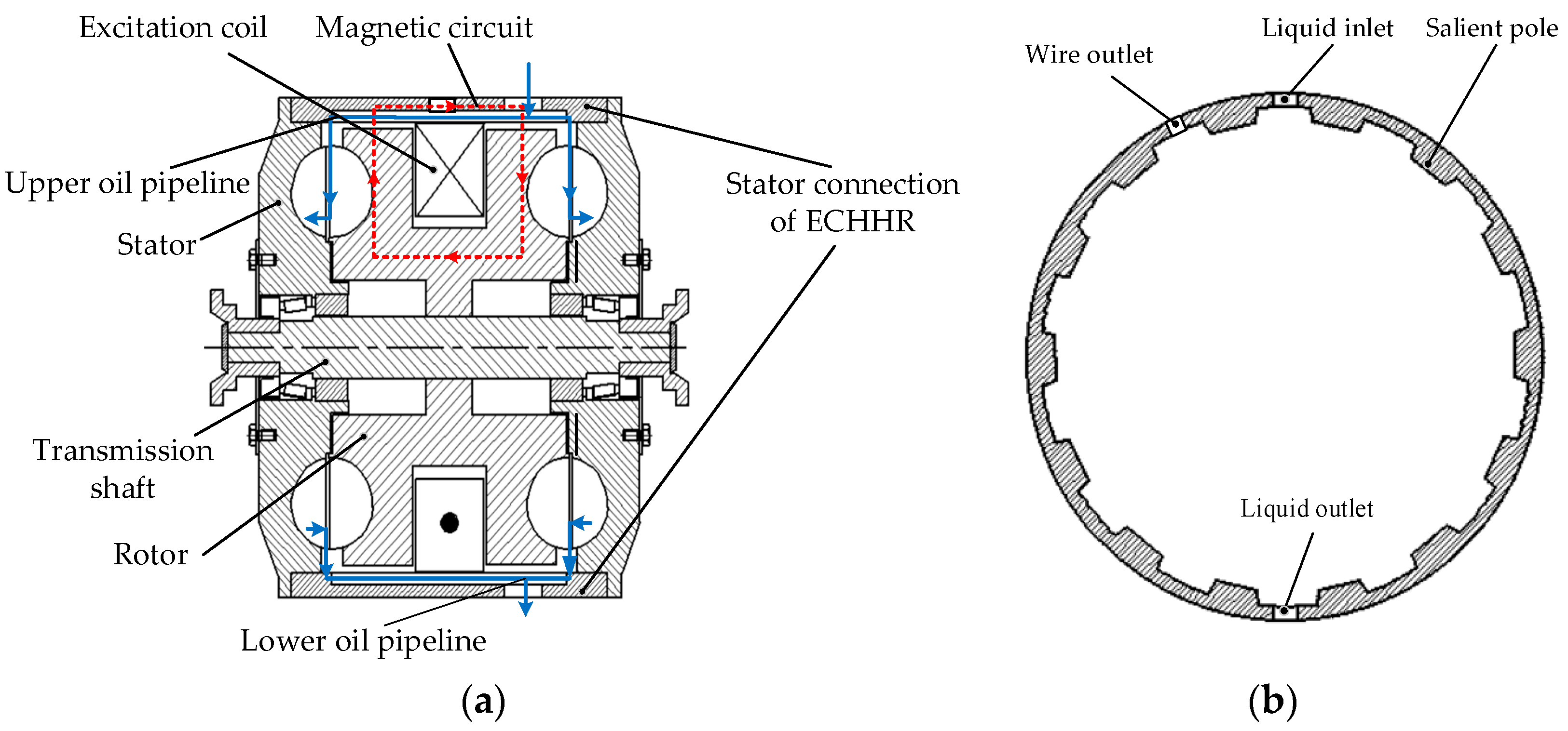
Figure 2.
Finite element simulation model of electromagnetic field of the ECHHR.
Figure 2.
Finite element simulation model of electromagnetic field of the ECHHR.
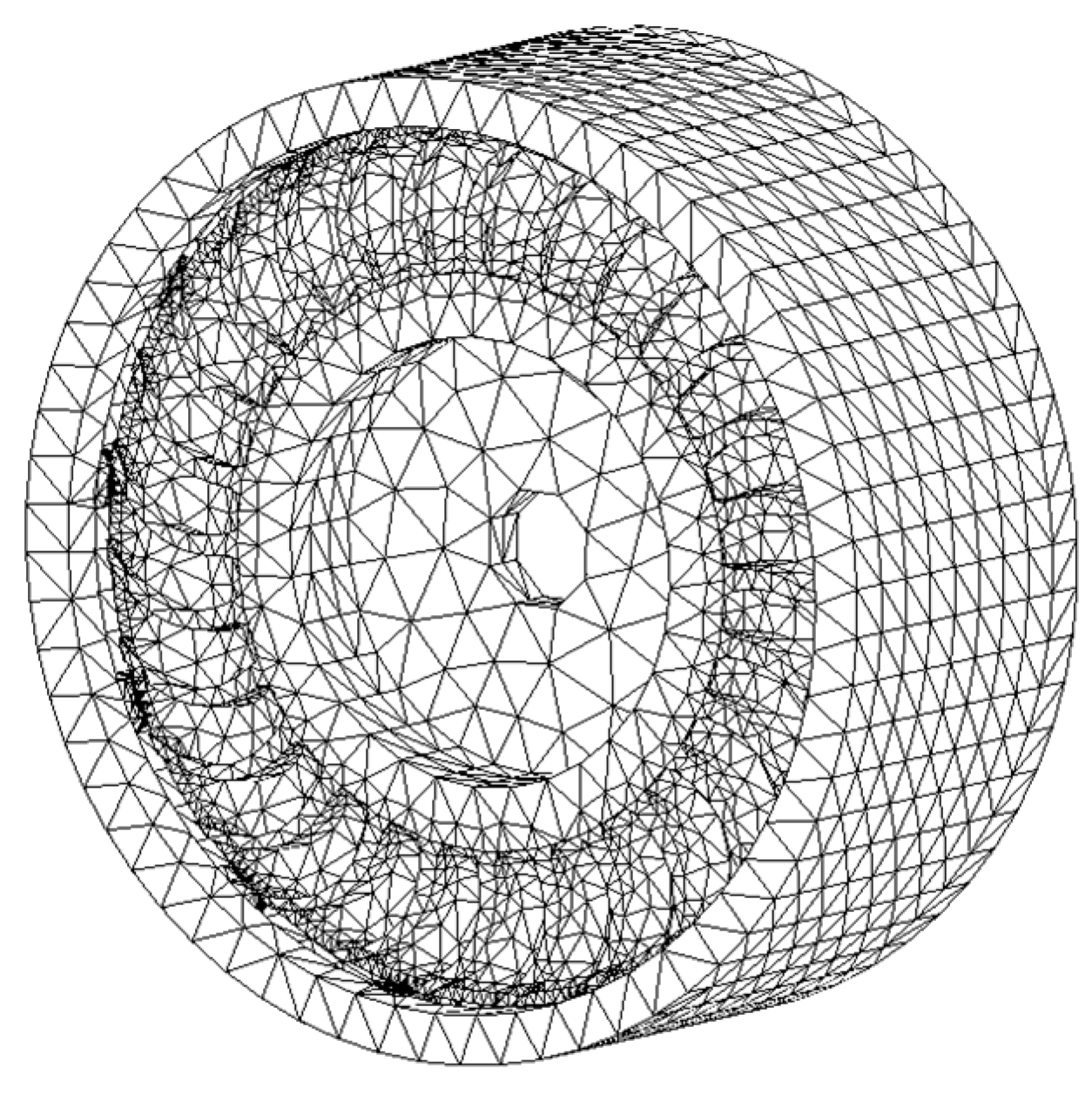
Figure 3.
The partial finite element analysis model.
Figure 3.
The partial finite element analysis model.
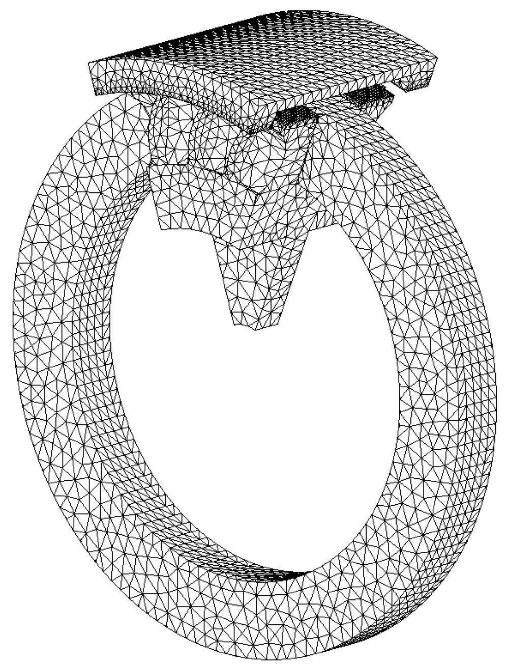
Figure 4.
(a) Magnetic field vector diagram. (b) Magnetic dense cloud diagram.
Figure 4.
(a) Magnetic field vector diagram. (b) Magnetic dense cloud diagram.
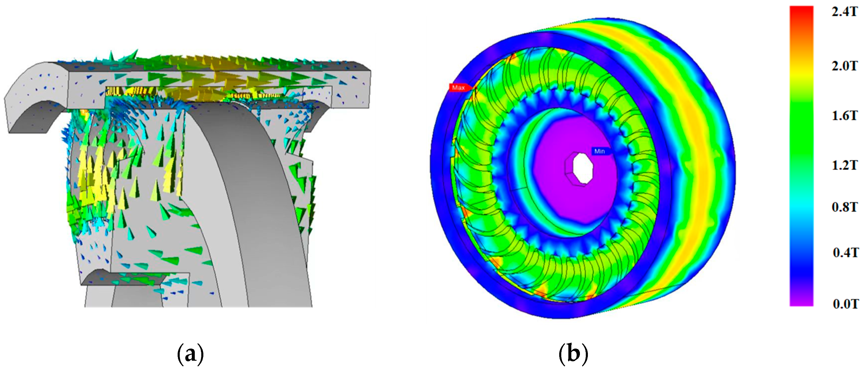
Figure 5.
Periodic static air gap magnetic density under different excitation currents.
Figure 5.
Periodic static air gap magnetic density under different excitation currents.
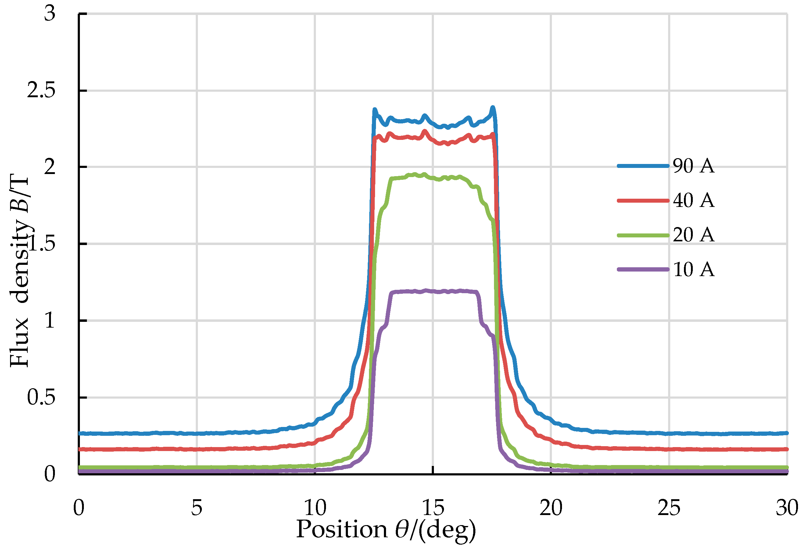
Figure 6.
Curve of eddy current braking torque under different excitation currents.
Figure 6.
Curve of eddy current braking torque under different excitation currents.
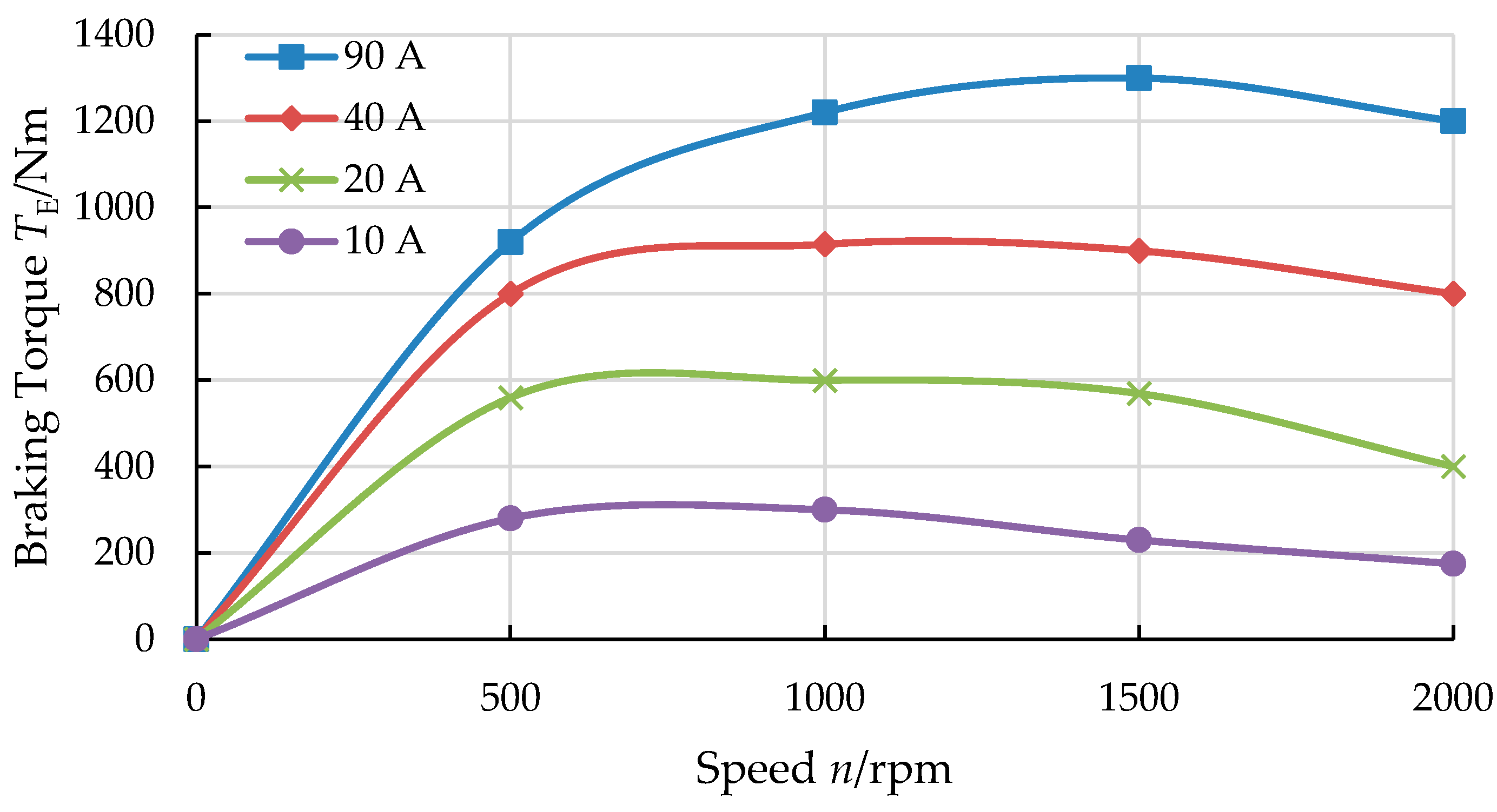
Figure 7.
CFD simulation model of flow field of ECHHR.
Figure 7.
CFD simulation model of flow field of ECHHR.
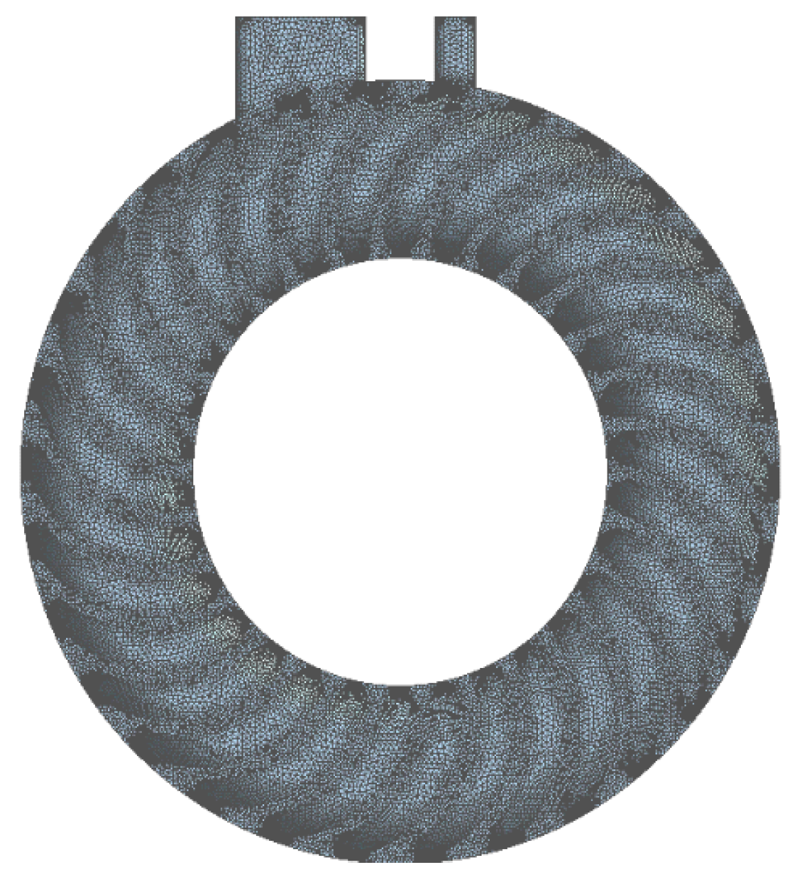
Figure 8.
Velocity vector diagram of flow field: (a) Rotor. (b) Stator.
Figure 8.
Velocity vector diagram of flow field: (a) Rotor. (b) Stator.
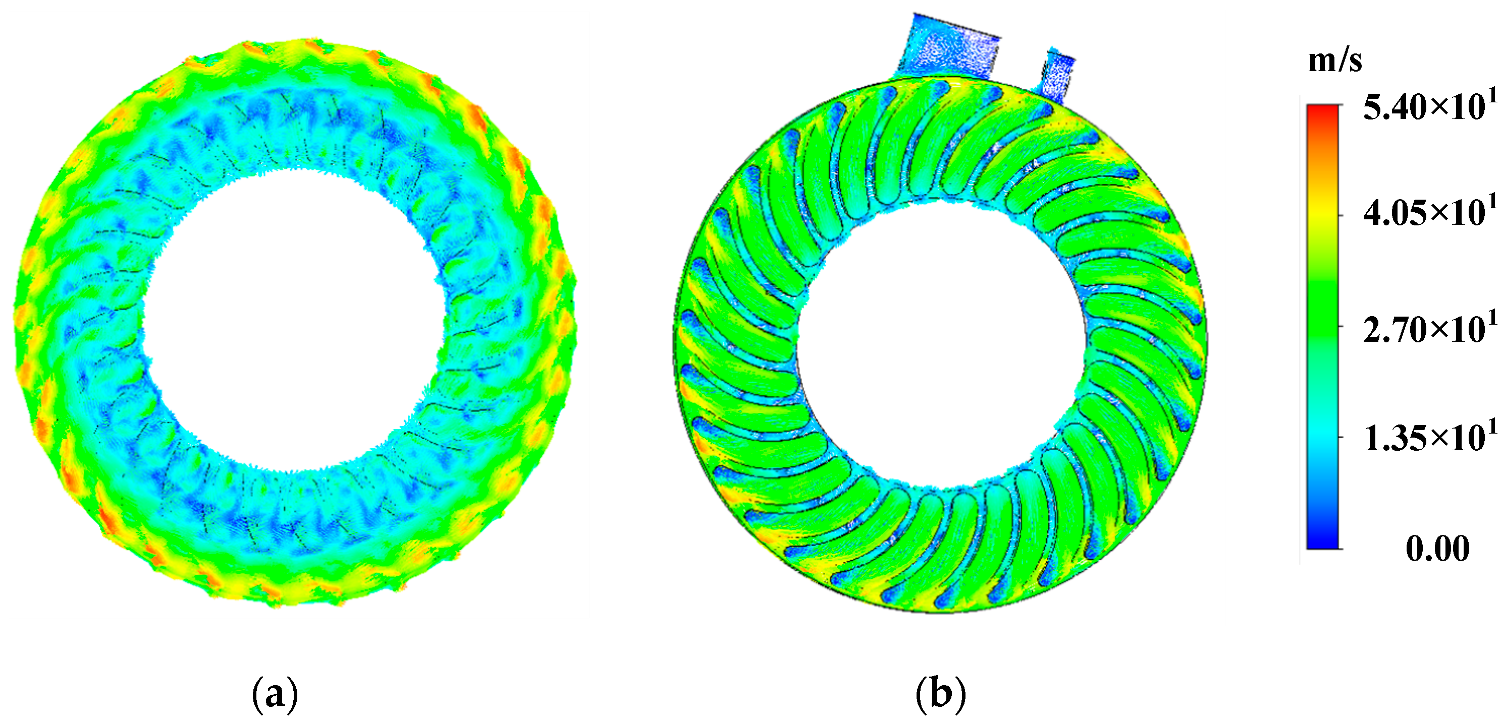
Figure 9.
Cloud chart of flow field pressure: (a) Rotor blade. (b) Stator blade.
Figure 9.
Cloud chart of flow field pressure: (a) Rotor blade. (b) Stator blade.
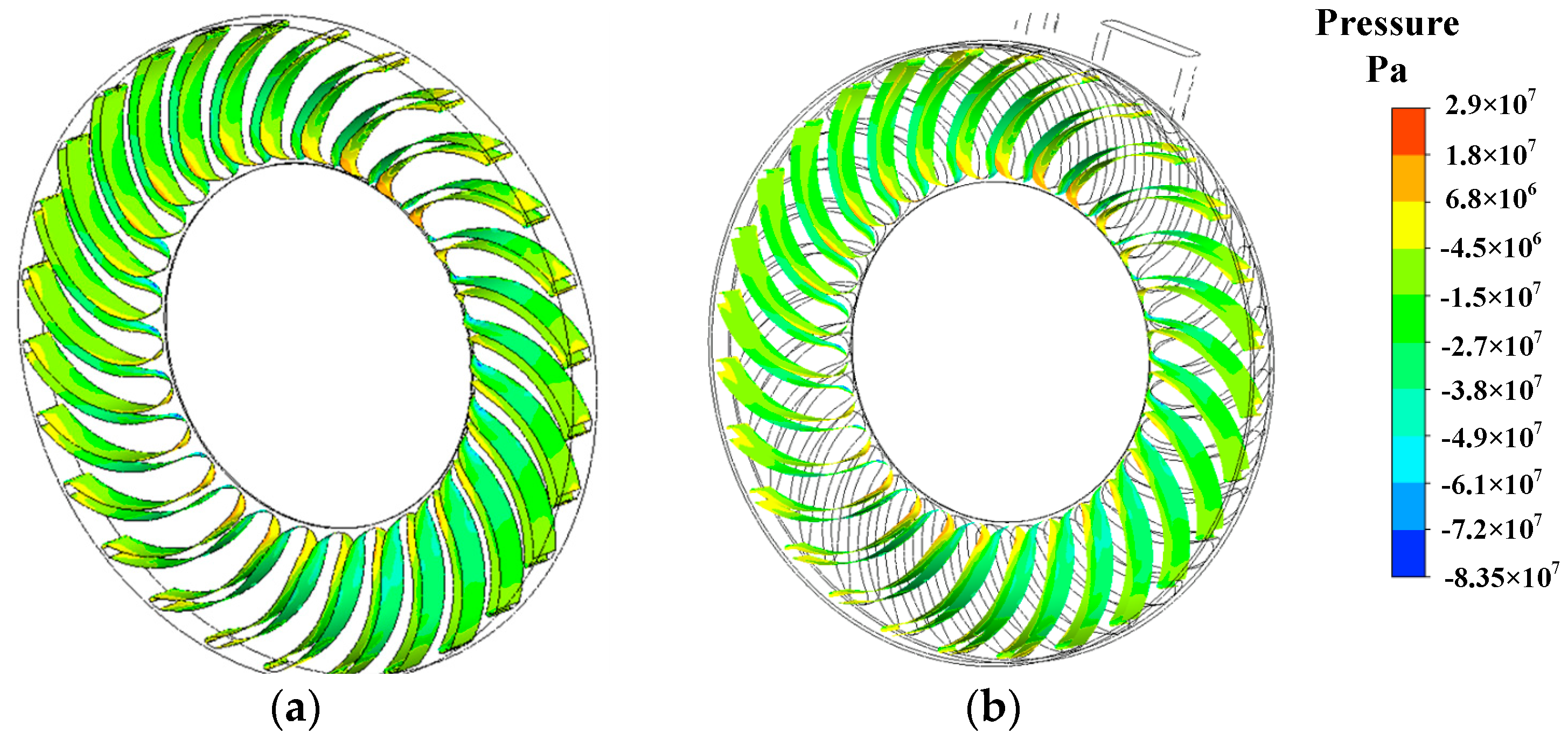
Figure 10.
Curve of hydraulic braking torque changing with fluid filling rate.
Figure 10.
Curve of hydraulic braking torque changing with fluid filling rate.
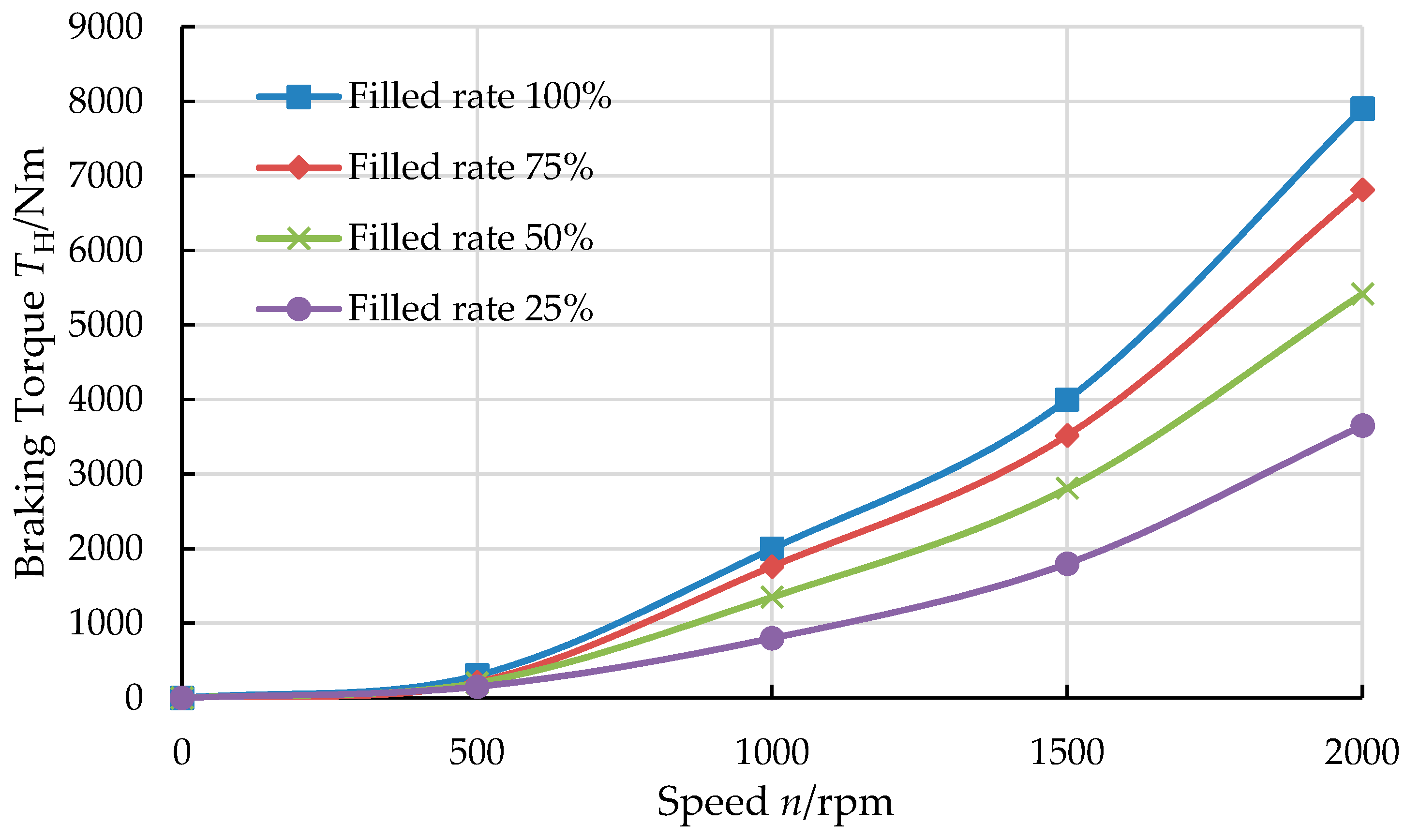
Figure 11.
Comparison curve of hydraulic brake, eddy current brake torque, and hydraulic electric composite brake torque.
Figure 11.
Comparison curve of hydraulic brake, eddy current brake torque, and hydraulic electric composite brake torque.
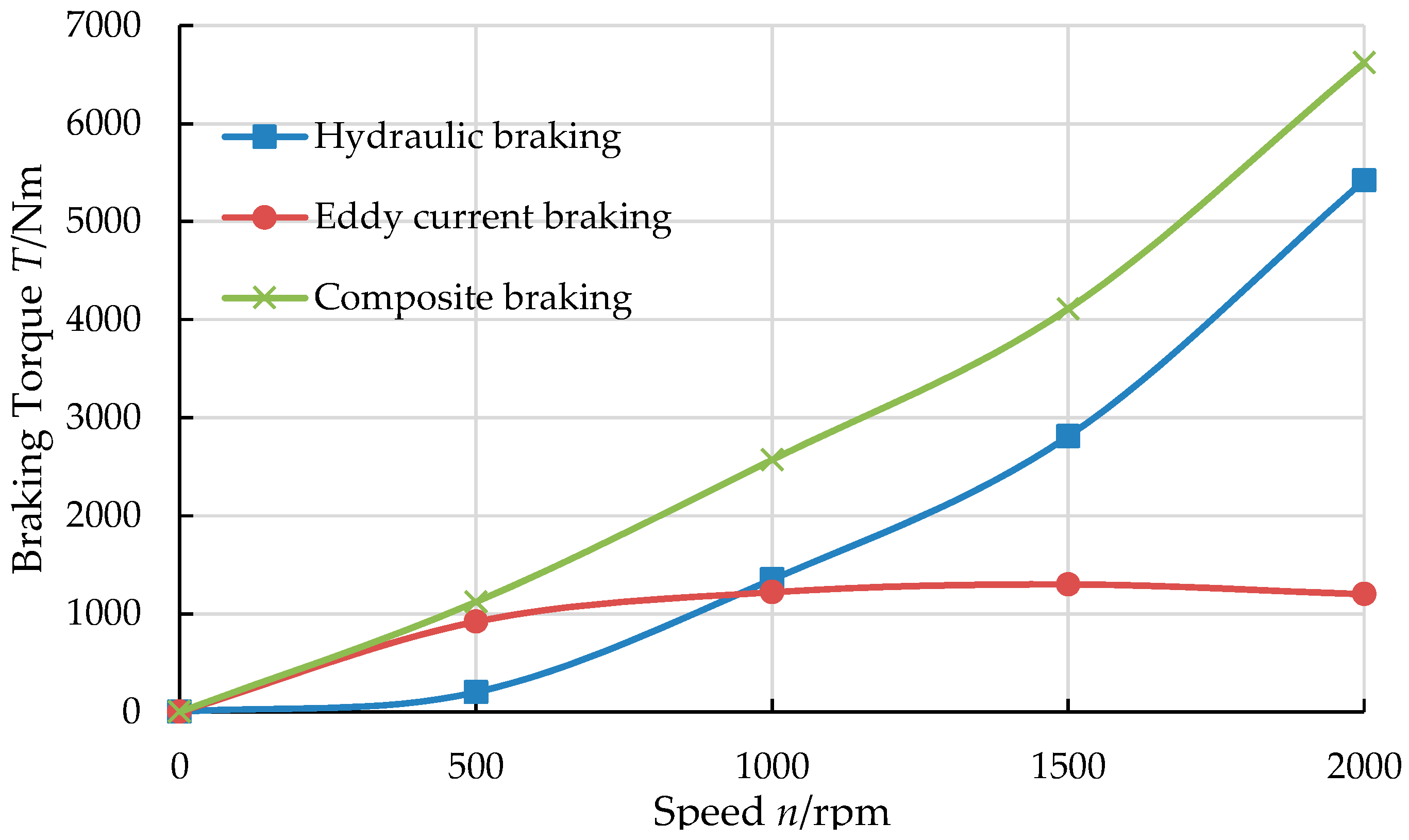
Figure 12.
Schematic diagram of the test bench.
Figure 12.
Schematic diagram of the test bench.
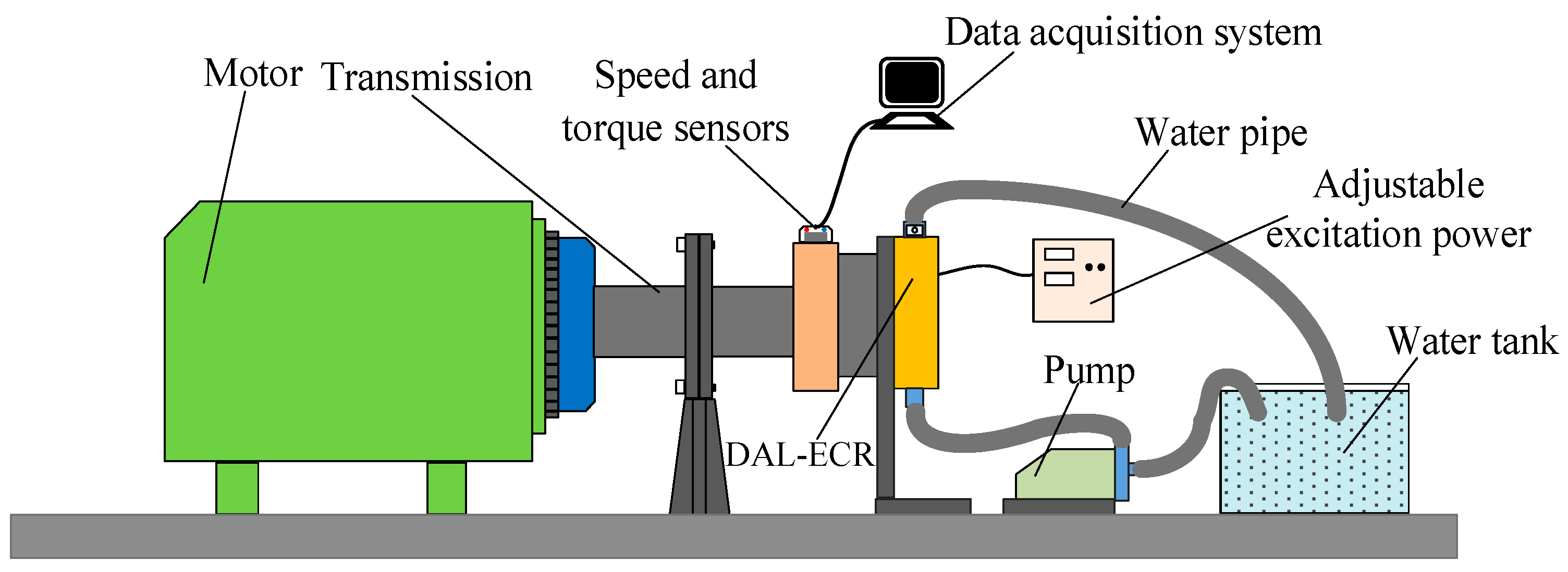
Figure 13.
ECHHR prototype.
Figure 13.
ECHHR prototype.
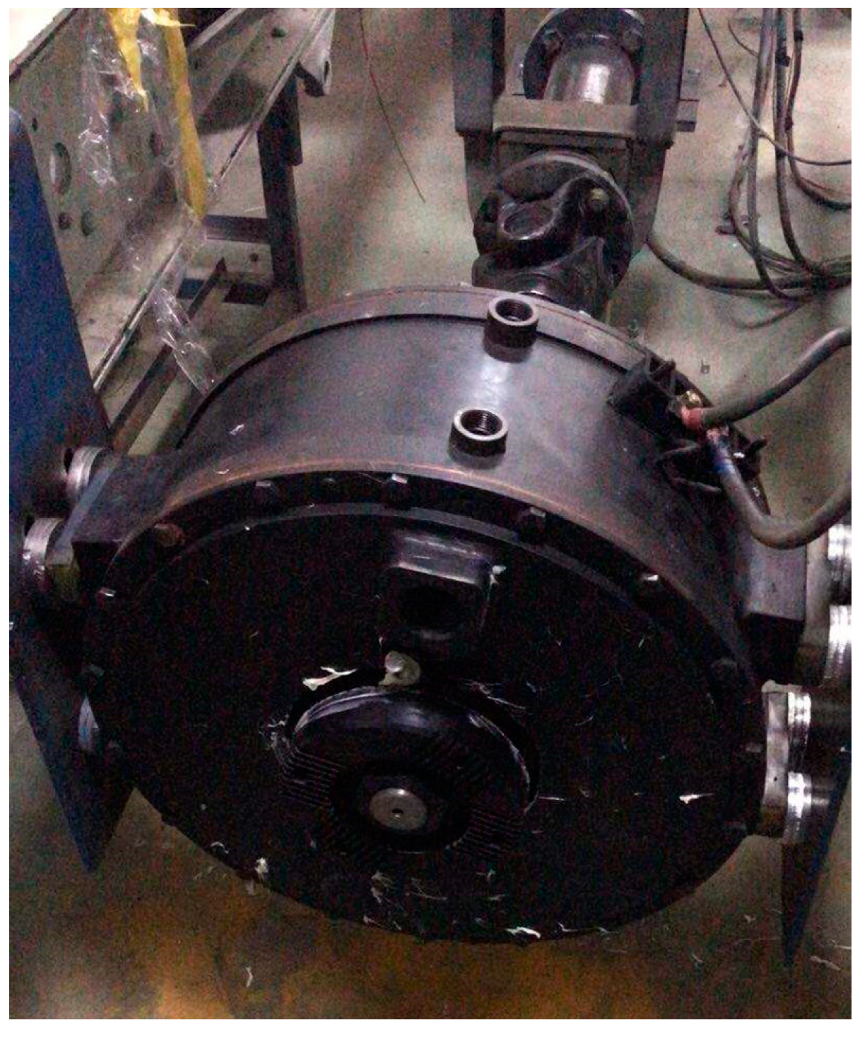
Figure 14.
Brake torque curves of different inlet pressure.
Figure 14.
Brake torque curves of different inlet pressure.
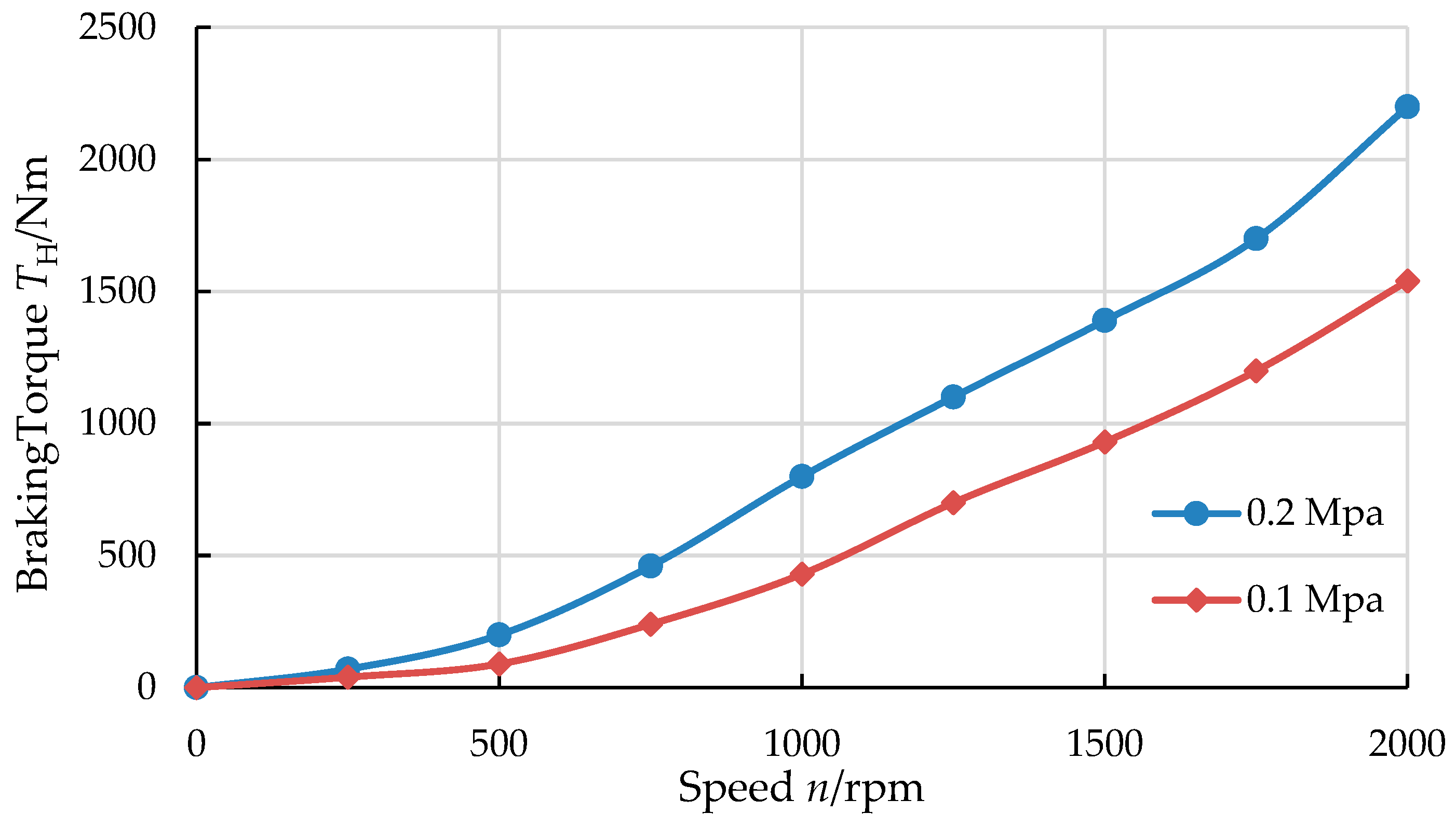
Figure 15.
Eddy current braking torque variation curve with rotational speed.
Figure 15.
Eddy current braking torque variation curve with rotational speed.
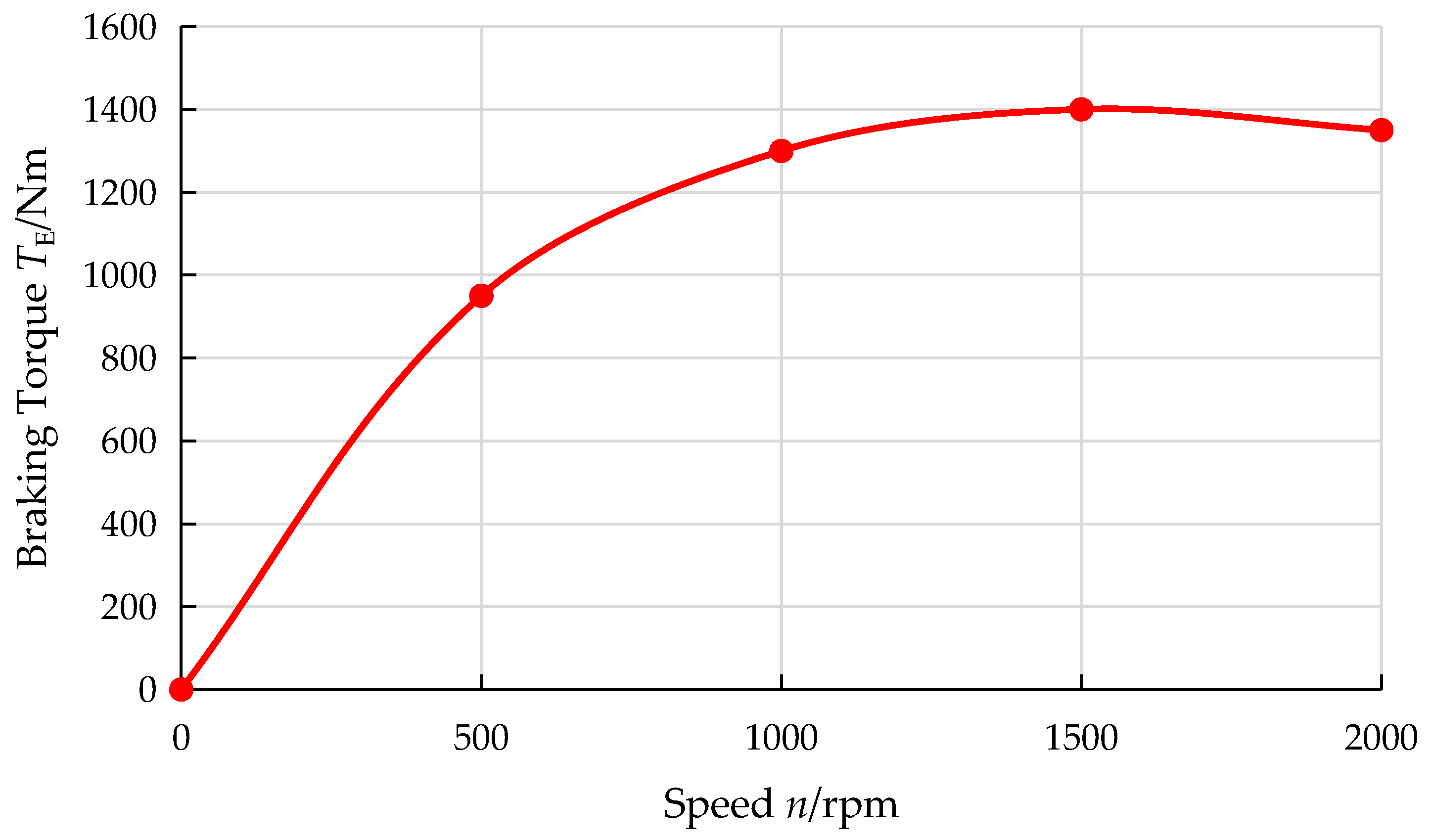
Figure 16.
Curve of composite braking torque variation with rotational speed.
Figure 16.
Curve of composite braking torque variation with rotational speed.
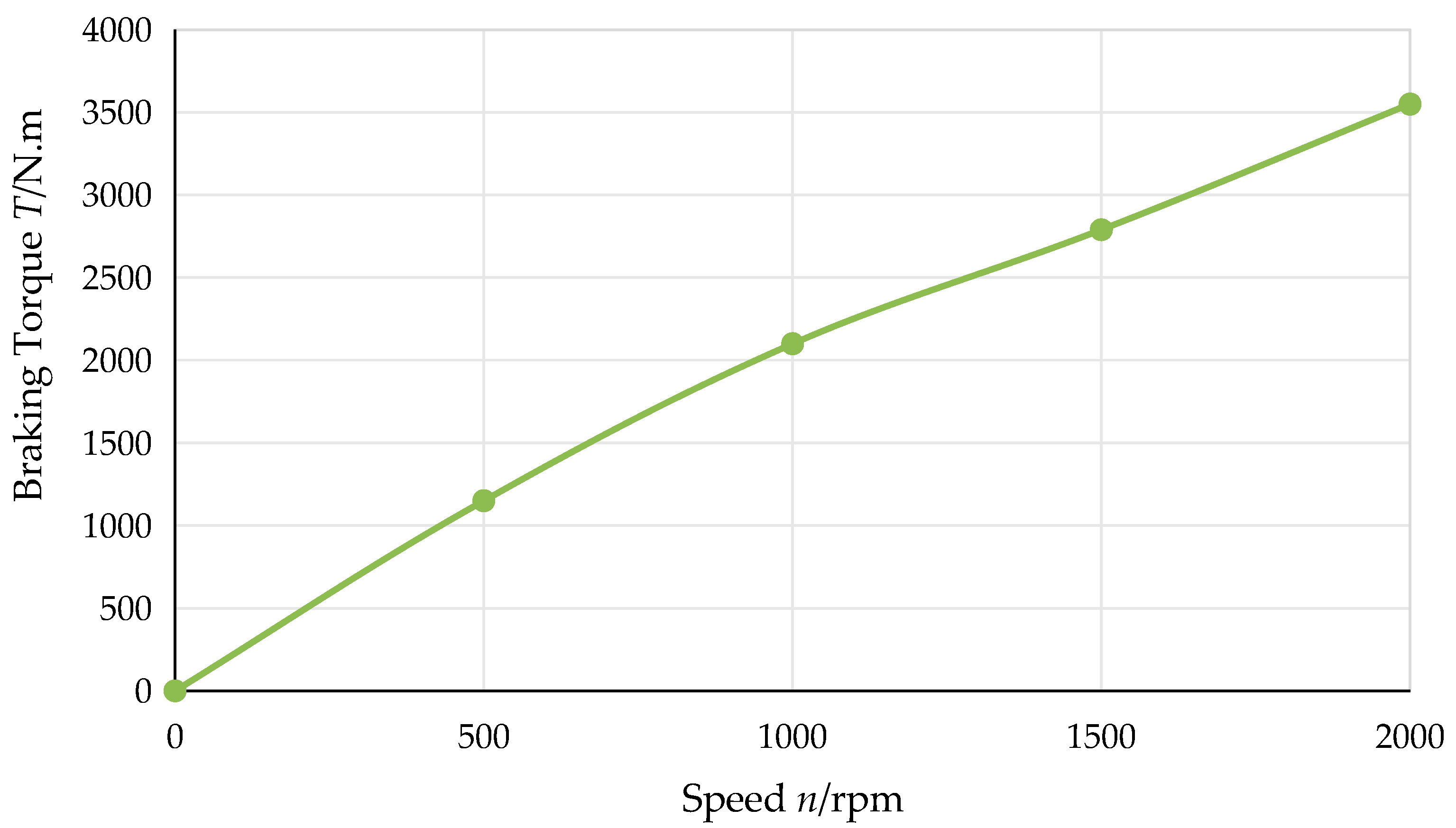
Figure 17.
Comparison of hydraulic braking torque test results with theoretical results.
Figure 17.
Comparison of hydraulic braking torque test results with theoretical results.
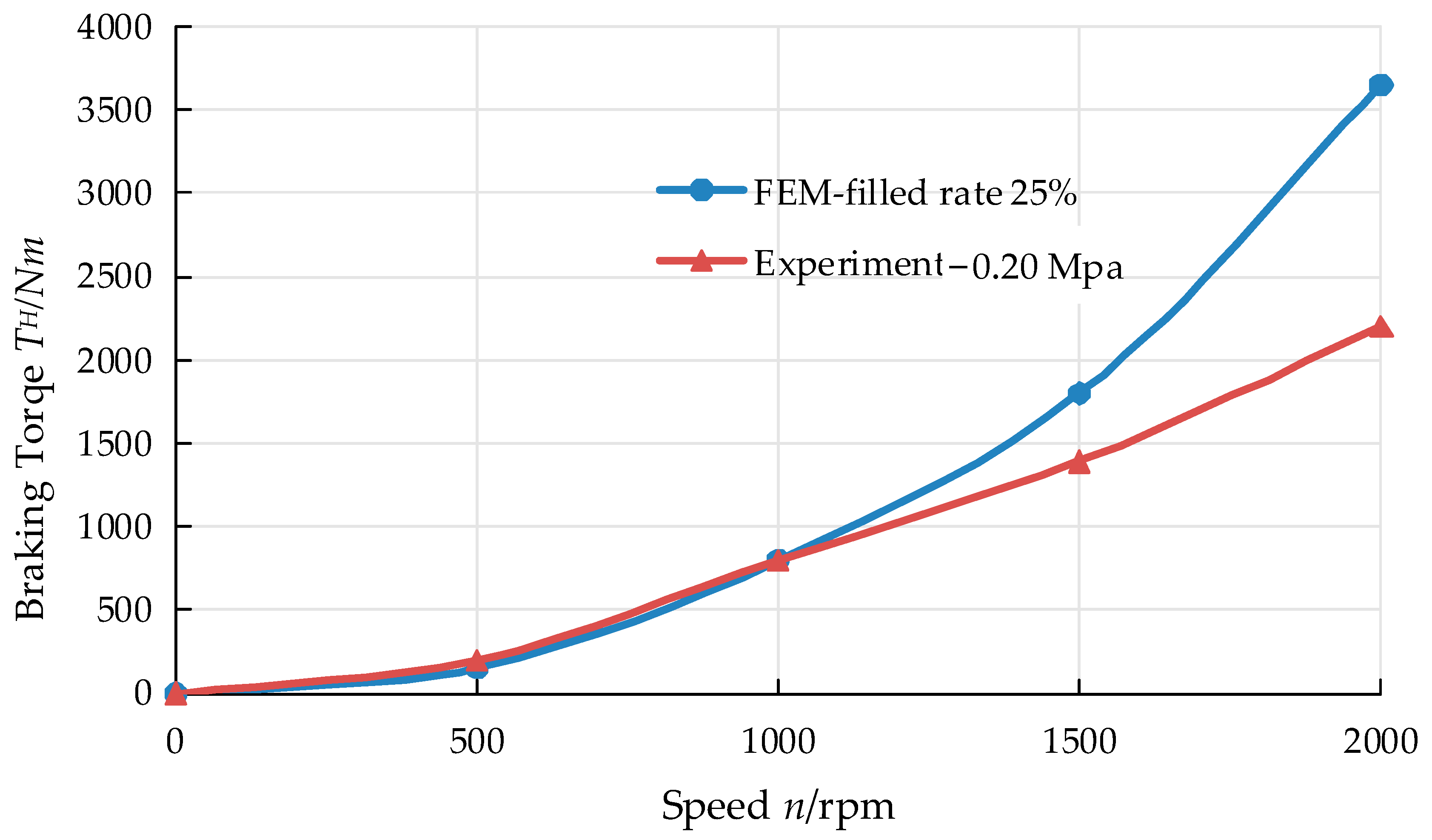
Figure 18.
No-load torque of the ECHHR.
Figure 18.
No-load torque of the ECHHR.
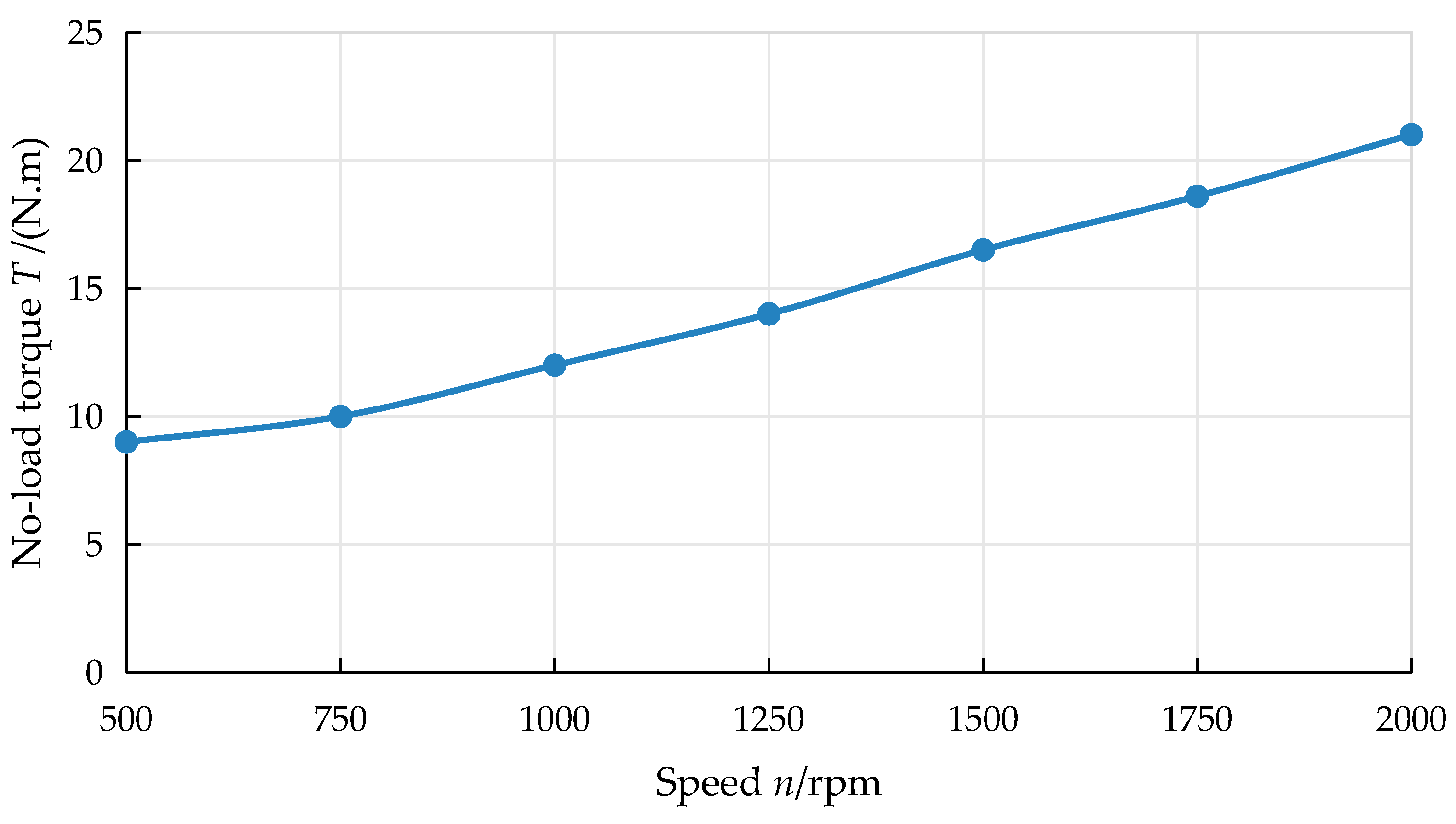
Figure 19.
Comparison of eddy current braking torque test results with theoretical results.
Figure 19.
Comparison of eddy current braking torque test results with theoretical results.
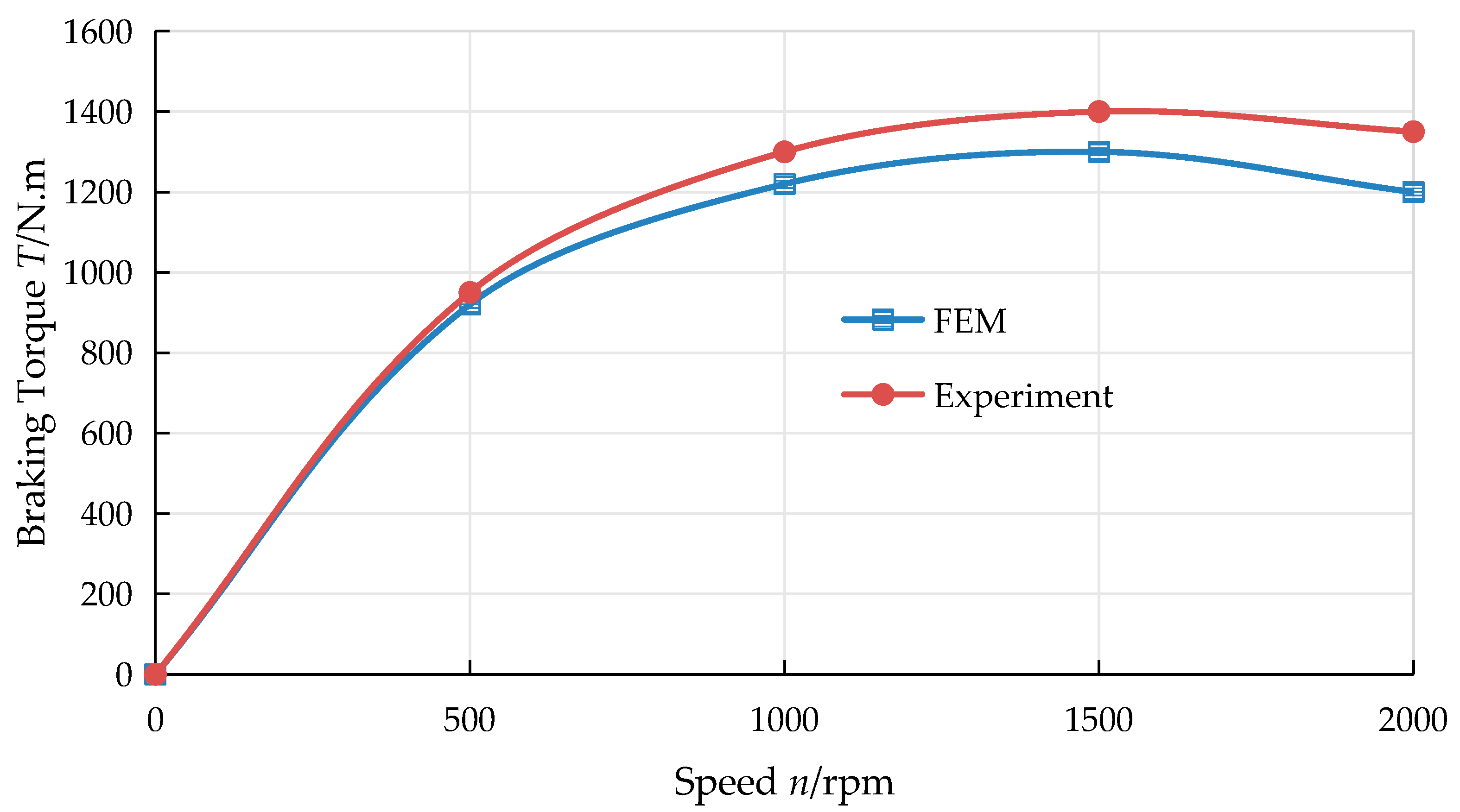
Table 1.
Design parameters of ECHHR.
Table 1.
Design parameters of ECHHR.
| Parameters | Value/Model |
|---|---|
| Outer diameter of stator/mm | 490 |
| Inner diameter of stator/mm | 200 |
| Outer diameter of rotor/mm | 440 |
| Inner diameter of rotor/mm | 224 |
| Axial length of one side stator/mm | 45 |
| Axial length of rotor/mm | 80 |
| Thickness of stator connection/mm | 25 |
| Stator material | Aluminum |
| Rotor material | 10CrMo |
| Material of stator connection | 10CrMo |
| Excitation coils | Copper |
| ECHHR quality/kg | 165 |
Table 2.
Geometric parameters of model.
Table 2.
Geometric parameters of model.
| Parameter | Stator Impeller | Rotor Impeller |
|---|---|---|
| Circular outer diameter/mm | 427 | 410 |
| Inside diameter of circular circle/mm | 290 | 290 |
| Number of blades | 27 | 28 |
| Blade thickness | 4.5 | 4.5 |
Table 3.
Boundary condition setting.
Table 3.
Boundary condition setting.
| Item | Parameter |
|---|---|
| Analysis type | Transient |
| Solution type | Based on pressure |
| Turbulence model | Realizable k-ε |
| Import boundary | 2.1 kg/s (Flow), 3 × 10⁵ pa (Pressure) |
| Exit boundary | 3.5 × 10⁵ pa (Pressure) |
| Stator and rotor domain | sliding mesh |
| Time step | 0.005 |
| Time step | 200 |
|
Disclaimer/Publisher’s Note: The statements, opinions and data contained in all publications are solely those of the individual author(s) and contributor(s) and not of MDPI and/or the editor(s). MDPI and/or the editor(s) disclaim responsibility for any injury to people or property resulting from any ideas, methods, instructions or products referred to in the content. |